


E6581301
L-3
12
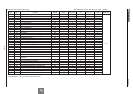
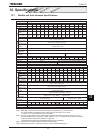
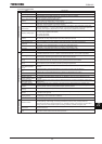
3) Common specification
Item Specification
Control specification
Control system Sinusoidal PWM control
Output voltage adjustment Main circuit voltage feedback control. (Switchable between automatic adjustment/fix/control off)
Output frequency range
Setting between 0.01 to 500Hz. Default max. frequency is set to 0.01 to 60Hz.
Maximum frequency adjustment (30 to 500Hz)
Minimum setting steps of
frequency
0.01Hz: operation panel input (60Hz base),
0.03Hz: analog input (60Hz base, 11 bit/0 to 10Vdc)
Frequency accuracy
Analog input: ±0.2% of the maximum output frequency (at 25±10°C)
Digital input: ±0.01%±0.022Hz of the output frequency
Voltage/frequency
characteristics
V/f constant, square reduction torque control, automatic torque boost, vector calculation control, base
frequency adjustment 1, 2, 3, and 4 (25 to 500Hz), V/f 5-point arbitrary setting, torque boost adjustment
(0 to 30%), start frequency adjustment (0 to 10Hz), stop frequency adjustment (0 to 30Hz)
Frequency setting signal
3k potentiometer (possible to connect to 1 to 10k-rated potentiometer)
0 to 10Vdc (input impedance Zin: 30k)
0 to ±10Vdc (Zin: 22k)
4 to 20mAdc (Zin:242)
Terminal board base
frequency
The characteristic can be set arbitrarily by two-point setting. Compliant with 6 types of input; analog input
(RR, VI/II, RX, AI1, AI2), and pulse input. (*AI1, AI2, pulse input: optional)
Frequency jump 3 places. Setting of jump frequency and width.
Upper and lower limit
frequencies
Upper limit frequency: 0 to max. frequency, lower limit frequency: 0 to upper limit frequency
PWM carrier frequency
200V-45kW or less, adjustable between 1.0 to 16kHz for 400V-75kW or less
200V-55kW or less, adjustable between 2.5 to 8kHz for 400V-90kW or more
PID control Adjustment of proportional gain, integral time, differential time and delay filter
Torque control Voltage command input specification: DC 0 to ±10V
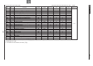
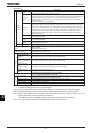
Operation specifications
Acceleration/deceleration
time
0.01 to 6000 sec. Selectable from among acceleration/deceleration. times 1, 2, 3 and 4. Automatic
acceleration/deceleration function. S-pattern acceleration/deceleration 1 and 2 pattern adjustable.
DC braking
Adjustment of braking start frequency (0 to 120Hz), braking (0 to 100%) and braking time (0 to 20 sec.).
With emergency stop braking function and motor shaft fix control function.
Forward run/reverse run
[Note 1]
With F-CC closed to forward run, with R-CC closed to reverse run, with both closed to reverse run. With
ST-CC opened to coast stop. Emergency stop by panel operation or terminal board.
Jog run
[Note 1]
Jog mode, if selected, allows jog operation from the operation panel
Jog run operation by terminal board is possible by setting the parameters.
Preset speed operation
[Note 1]
By changing the combination of open/close between S1, S2, S3, RR/S4-CC, set frequency + 15-speed
operation.
Selectable between acceleration/deceleration time, torque limit and V/f by set frequency.
Retry
Capable of restarting after a check of the main circuit elements in case the protective function is
activated. Max. 10 times selectable arbitrarily. Waiting time adjustment (0 to 10 sec.)
Soft stall Automatic load reduction control at overloading. (Default: OFF)
Cooling fan ON/OFF The cooling fan will be stopped automatically to assure long life when unnecessary.
Operation panel key
operation ON/OFF control
Key prohibition selectable between STOP key only, MODE key only, etc. All key operations can be
prohibited.
Regenerative power
ride-through control
Possible to keep the motor running using its regenerative energy in case of a momentary power failure.
(Default: OFF)
Auto-restart operation Possible to restart the motor in coasting in accordance with its speed and direction. (Default: OFF)
Simplified pattern
operation
Possible to select each 8 patterns in 2 groups from 15-speed operation frequency. Max. 16 types of
operation possible. Terminal board operation/repeat operation possible.
Commercial inverter
switching
Possible to switch operation by commercial power source or inverter
Light-load high-speed
operation
Increases the operating efficiency of the machine by increasing the rotational speed of the motor when it
is operated under light load.
Drooping function
When two or more inverters are used to operate a single load, this function prevents load from
concentrating on one inverter due to unbalance.
Override function External input signal adjustment is possible to the operation frequency command value.
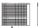
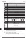
Protective function
Protective function
Stall prevention, current limit, overcurrent, overvoltage, short circuit on the load side, ground fault on the
load side [Note 5], undervoltage, momentary power failure (15ms or more), non-stop control at
momentary power failure, overload protection, arm overload at starting, overcurrent on the load side at
starting, overcurrent and overload at dynamic braking resistance, overheat, emergency stop
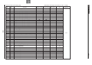
Electronic thermal
characteristic
Switchable between standard motor/constant torque VF motor, adjustment of overload protection and
stall prevention level.
Reset
Reset by 1a contact closed (or 1b contact opened), or by operation panel. Or power source OFF/ON.
This function is also used to save and clear trip records.
(Continued overleaf)