


K-15
E6581301
11
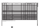
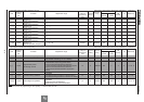
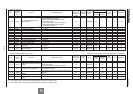
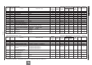
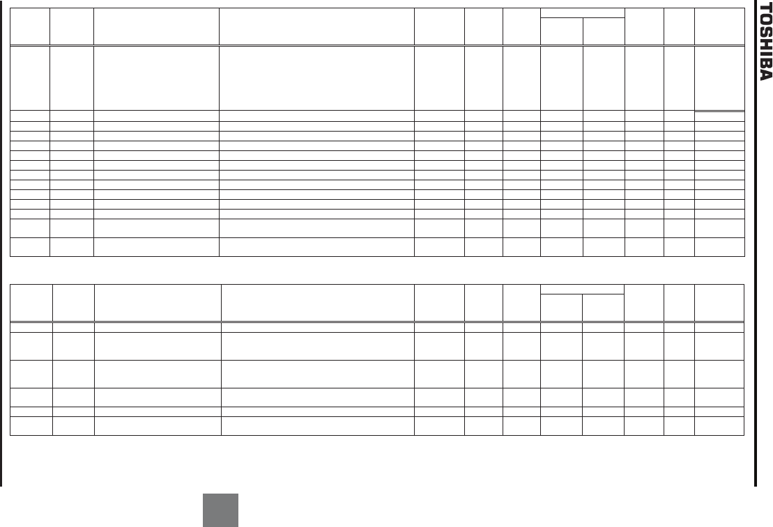
[16] PID control [2/2] Sensorless vector/vector with sensor (Ɣ:Effective, -:Ineffective)
Title
Communi
cation
No.
Function Adjustment range
Minimum
setting unit
(Panel/Communi
cation)
Default
setting
Write during
running
Vector control
PM
control
V/f Reference
Speed
control
Torque
control
H
0360
PID control feedback control
signal selection
0:Deviation input (no feedback input)
1:VI/II (voltage/current input)
2:RR/S4 (potentiometer/voltage input)
3:RX (voltage input)
4:Optional AI1 (differential current input)
5:Optional AI2 (voltage/current input)
6:
PG
feedback
o
ption
1/1 0 Disabled Ɣ/Ɣ - Ɣ Ɣ *1, *2
H
0361
Delay filter
0.
0
~
25
.0
1/1
0.1
Enabled
Ɣ/Ɣ
-
Ɣ
Ɣ
*
2
H
0362
Proportional (P) gain
0.01~10
0.0
0.01/0.01
0.
1
0
Enabled
Ɣ/Ɣ
-
Ɣ
Ɣ
*1
, *2
H
0363
Integral (I) gain
0.01~100.0
0.01/0.01
0.
1
0
Enabled
Ɣ/Ɣ
-
Ɣ
Ɣ
*
2
H
0364
PID deviation upper limit
NN
~
WN
Hz
0.1/0.01
60.0
Enabled
Ɣ/Ɣ
-
Ɣ
Ɣ
*
2
H
0365
PID deviation lower limit
NN
~
WN
Hz
0.1/0.01
60.0
Enabled
Ɣ/Ɣ
-
Ɣ
Ɣ
*
2
H
0366
Differential (D) gain
0.00~2.55
0.01/0.01
0.00
Enabled
Ɣ/Ɣ
-
Ɣ
Ɣ
*
2
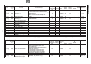
H
0367
Process upper limit
NN
~
WN
Hz
0.1/0.01
60.0
Enabled
Ɣ/Ɣ
-
Ɣ
Ɣ
*
2
H
0368
Process lower limit
NN
~
WN
Hz
0.1/0.01
0.0
Enabled
Ɣ/Ɣ
-
Ɣ
Ɣ
*
2
H
0369
PID control waiting time
0~2400 sec.
1
/1
0
Enabled
Ɣ/Ɣ
-
Ɣ
Ɣ
*
2
H
0370
PID output upper limit
NN
~
WN
Hz
0.1/0.01
60.0
Enabled
Ɣ/Ɣ
-
Ɣ
Ɣ
*
2
H
0371
PID output lower limit
NN
~
WN
Hz
0.1/0.01
0.0
Enabled
Ɣ/Ɣ
-
Ɣ
Ɣ
*
2
H
0372
Process increasin
g rate (speed type
PID control)
0.1~600.0 0.1/0.1 10.0 Enabled Ɣ/Ɣ - Ɣ Ɣ *2
H
0373
Process decreasing rate (speed
type PID control)
0.1~600.0 0.1/0.1 10.0 Enabled Ɣ/Ɣ - Ɣ Ɣ *2
*1: For details, refer to Instruction Manual (E6581319) specified in Section 6.42. *2: For details, refer to Instruction Manual (E6581329) specified in Section 6.42.
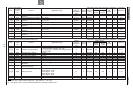
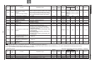
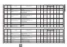
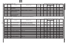
[17] Speed feedback/positioning control Sensorless vector/vector with sensor (Ɣ:Effective, -:Ineffective)
Title
Communi
cation
No.
Function Adjustment range
Min
imum
setting unit
(Panel/Communi
cation)
Default
setting
Write during
running
Vector control
PM
control
V/f Reference
Speed
control
Torque
control
H
0375
Number of PG input pulses
1
~9999
1/1
500
Disabled
-
/
Ɣ
-
/
Ɣ
-
-
*1
H
0376
Selection of number of PG input
phases
1:Single
-
phase input
2:Two-phase input
3
:Two
-
phase input
(Inversion of polarity)
1/1 2 Disabled -/Ɣ -/Ɣ - - *1
H
0377 PG disconnection detection
0:Disabled
1:Enabled (with filter)
2:
Enabled
(
Detection of momentary power fa
ilure
)
1/1 0 Disabled -/Ɣ -/Ɣ - - *1
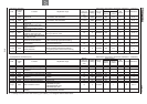
H
0378
Number of RP terminal input
pulses
1~9999 1/1 500 Disabled Ɣ/Ɣ Ɣ/Ɣ Ɣ Ɣ *2
H
0379
PID
output dead band
0~100
%
1/1
0
Enabled
Ɣ
/
Ɣ
Ɣ
/
Ɣ
Ɣ
Ɣ
*3
H
0381
Simple positioning completion
range
1~4000 1/1 100 Enabled -/Ɣ - - - *1
*1: For details, refer to Instruction Manual (E6581319) specified in Section 6.42.
*2: For details, refer to Instruction Manual (E6581341) specified in Section 6.42.
*3: For details, refer to Instruction Manual (E6581329) specified in Section 6.42.