


E6581301
E-11
5
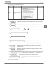
5.6 Selecting control mode
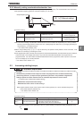
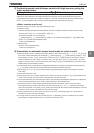
RV
RVRV
RV : V/f control mode selection
[Parameter setting]
Title Function Adjustment range Default setting
RV V/f control mode selection
: Constant torque characteristics
: Voltage decrease curve
: Automatic torque boost
: Sensorless vector control 1
: Sensorless vector control 2
: V/f 5-point setting
: PM control
: PG feedback control
: PG feedback vector control
Caution
Mandatory
• When operating the inverter with RV set to , , , or , be sure to set the motor constant
parameter correctly. Failure to do this may cause the inverter not to control the motor properly,
and thus cause the motor not to deliver the desired performance. For more information, see the
explanation of each RV setting in the following sections.
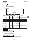
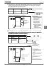
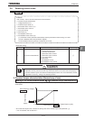
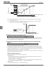
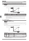
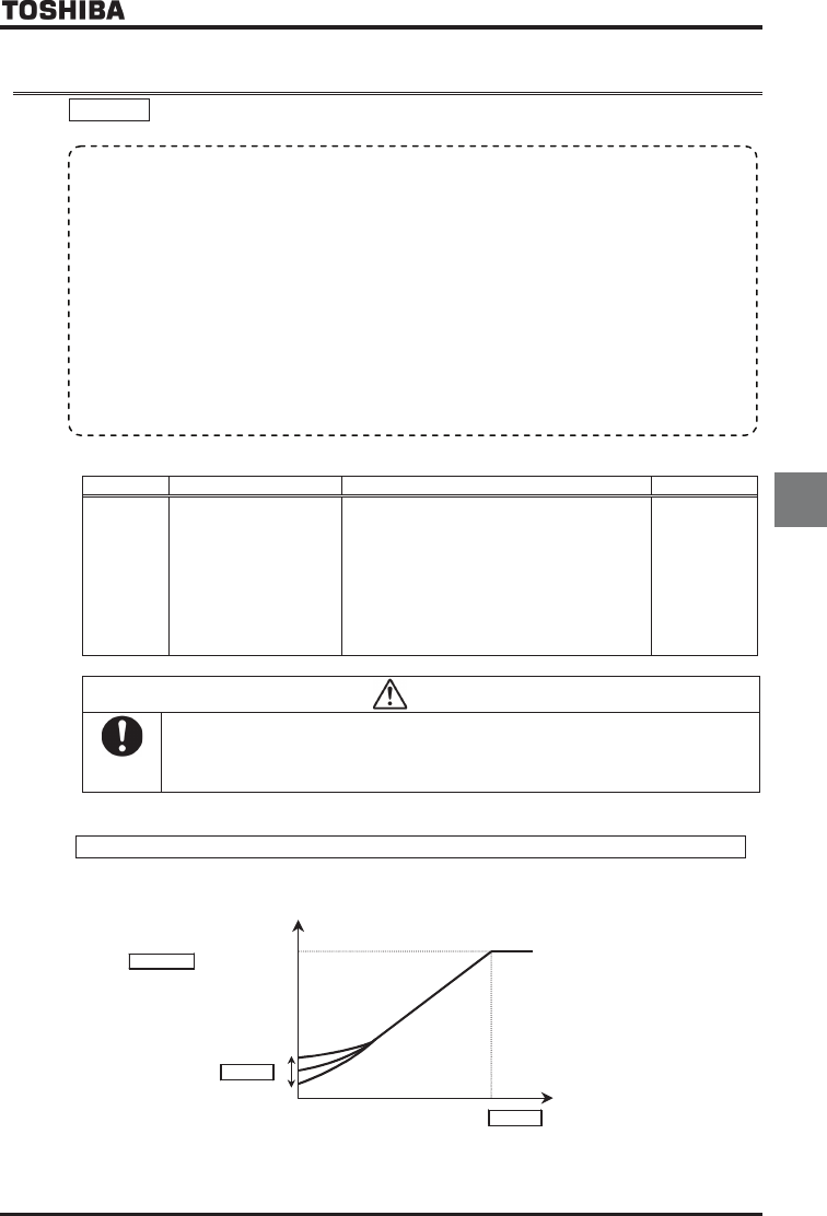
1) Constant torque characteristics (Normal way of use)
Setting of V/f control mode selection RV
RVRV
RV=
(Constant torque characteristics)
This is applied to loads with equipment like conveyors and cranes that require the same torque at low speeds as at
rated speeds.
Base frequency voltage 1
XNX
Output frequency [Hz]
XD
Base frequency
XN
0
Output voltage
[V]/[%]
* To increase the torque further, increase the setting value of the manual torque boost parameter XD.
For more details, refer to Section 5.7.
• Function
With “VF-AS1,” the V/f controls shown below can be selected.
0: Constant torque characteristics
1: Voltage decrease curve
2: Automatic torque boost (*1)
3: Sensorless vector control 1 (*1)
4: Sensorless vector control 2
5: V/f 5-point setting
6: PM control (*2)
7: PG feedback control (*3)
8: PG feedback vector control (*3)
(*1) “Automatic control” parameter automatically sets this parameter and auto-tuning 1 at a time.
(
*
2) Use a dedicated motor with permanent magnets.
(
*
3) A PG feedback device (optional) is needed for this control.