E6581301
I-7
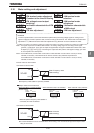
9
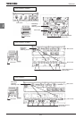
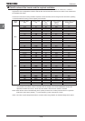
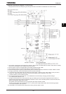
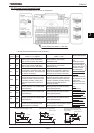
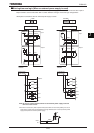
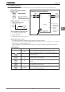
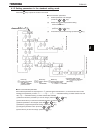
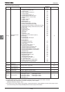
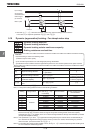
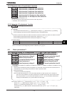
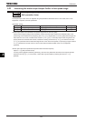
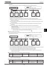
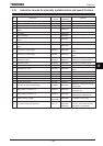
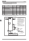
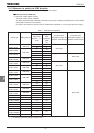
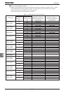
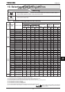
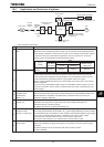
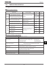
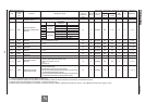
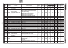
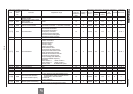
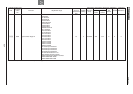
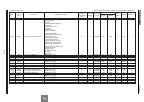
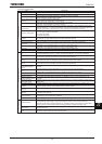
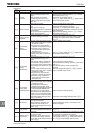
[Accessories for countermeasure]
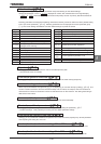
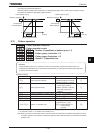
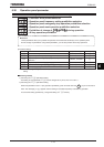
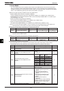
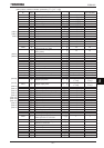
Ƒ Recommended shield cable : Showa electric Wire & Cable Co., LTD
Type : CV-S
Rating : 600V or less
Cross-sectional area : 2~1000mm
2
If it is difficult to procure shielded cables, protect cables with conduit tubes.
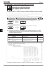
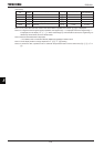
Ƒ [Note 1] Recommended shield : SUMITOMO 3M Limited, Electromagnetic wave guard shielding sleeve
Type : DS-5, 7, 10, 14
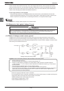
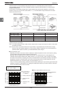
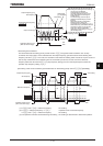
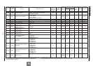
Ƒ EMC filter Type : EMF3 series
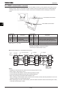
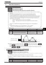
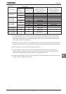
Ƒ Recommended ferrite core 1 : TDK Corporation
Type : ZCAT3035-1330
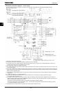
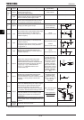
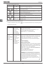
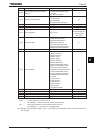
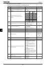
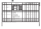
Use the following, as required.
Ƒ Recommended ferrite core : NEC TOKIN Corporation
Type : ESD-R-47D-1
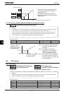
Ƒ Zero-phase reactor : Soshin Electric Co., Ltd.
Type : RC5078 or RC9129
Ƒ High-attenuation radio noise reduction filter : Soshin Electric Co., Ltd.
Type : NF series
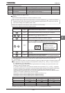
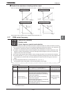
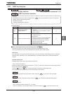
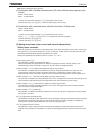
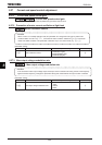
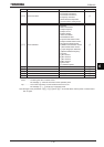
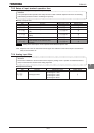
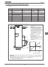
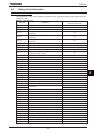
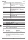
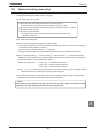
9.1.3 Low-voltage directive
The low-voltage directive provides for the safety of machines and systems. All Toshiba inverters are CE-marked in
accordance with the standard IEC61800-5-1 specified by the low-voltage directive, and can therefore be installed in
machines or systems and imported without a problem to European countries.
Applicable standard: IEC61800-5-1
Adjustable speed electrical power drive system
Pollution level: 2
Overvoltage category: 3
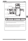
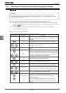
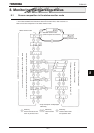
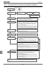
9.1.4 Measures to be taken to satisfy the low-voltage directive
When incorporating the inverter into a machine or system, it is necessary to take the following measures so that the
inverter satisfies the low-voltage directive.
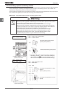
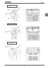
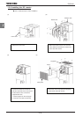
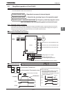
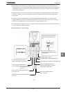
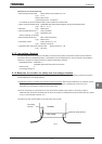
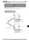
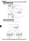
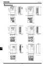
(1) Install the inverter in a cabinet and ground the inverter enclosure. When doing maintenance, be extremely careful
not to put your fingers into the inverter through a wiring hole and touch a charged part, which may occur
depending on the model and capacity of the inverter used.
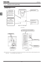
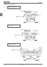
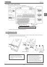
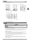
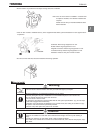
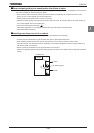
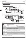
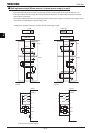
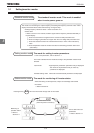
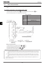
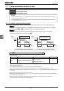
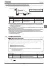
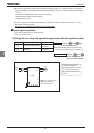
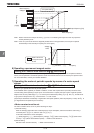
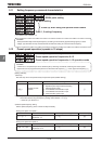
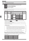
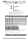
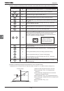
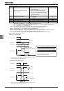
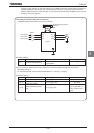
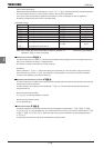
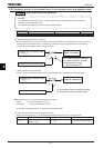
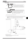
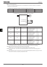
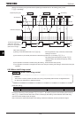
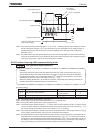
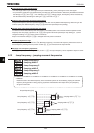
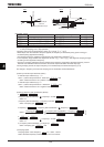
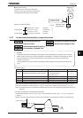
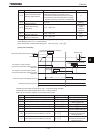
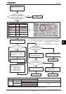
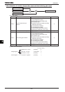
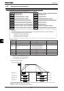
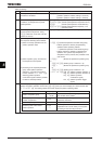
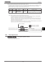
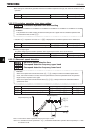
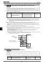
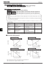
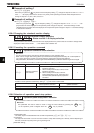
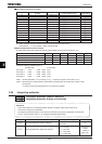
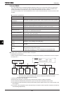
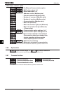
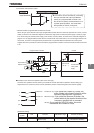
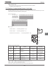
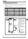
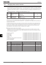
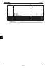
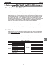
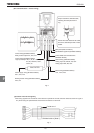
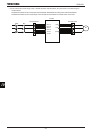
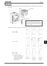
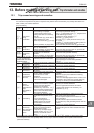
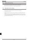
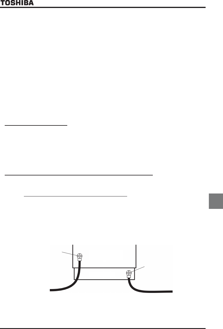
(2) Do not connect two or more wires to the main circuit earth terminal of the inverter. If necessary, install an
additional earth terminal on the EMC plate on which the inverter is installed and connect another cable to it. (Refer
to Fig. 4.) See the table of section 10.1.
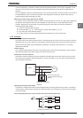
(3) Install a non-fuse circuit breaker on the input side of the inverter.
Inverter
Grounding
terminal
Install an earth terminal.
Fig. 4