


E6581301
B-7
2
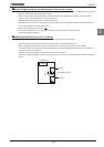
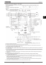
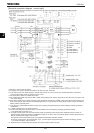
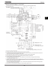
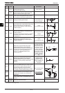
[Standard connection diagram - source logic]
The figure below shows an example of typical wiring in the main circuit 200V 0.4-45kW/400V 0.75-75kW inverter.
*1: The inverter is shipped with the terminals PO and PA/+ shorted with a bar (200V-45kW or smaller, 400V-75kW or smaller).
Remove this shorting bar when installing a DC reactor (DCL).
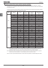
*2: The DC reactor is built in for models 200V-11kW~45kW and 400V-18.5kW~75kW.
*3: The noise filter is built in for models 200V-45kW or smaller and all of 400V.
*4: External braking resistor (option). Dynamic braking drive circuit built-in (GTR7) as standard for models 160kW or smaller.
*5: To supply a DC power, connect the cables to the PA/+ and PC/- terminals.
*6: If you want to use a DC power supply to operate the inverter (200V: 18.5kW or more, 400V: 22kW or more), be sure to
contact your Toshiba distributor, because an inrush current limiting circuit is required in such a case.
*7: Refer to Section 2.3.2 for switch functions.
*8: The functions assigned to terminals OUT1, VI/II and RR/S4 can be switched by changing parameter settings.
For details refer to Section 2.3.2.
*9: To supply control power from an external power supply for backing up the control power supplied from the inverter, an
optional control power backup device (CPS002Z) is required. In such a case, the backup device is used at the same time
with the internal power supply of the inverter.
The optional control power backup unit can be used with both 200V and 400V models.
To back up control power, set the parameter H (Control power supply backup option failure monitoring) properly.
For more information, refer to 6.33.24.
*10: When RES-CC is shorted and then opened, the inverter protective status is reset.