


E6581301
E-12
5
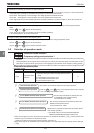
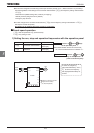
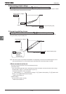
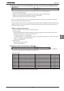
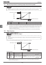
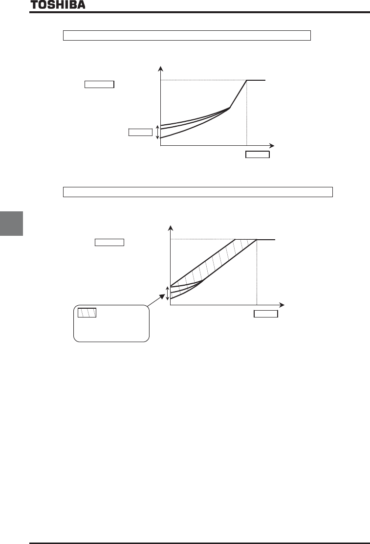
2) Decreasing output voltage
Setting of V/f control mode selection RV
RVRV
RV=
(Voltage decrease curve)
This is appropriate for load characteristics of such things as fans, pumps and blowers in which the torque in relation
to load rotation speed is proportional to its square.
Base frequency voltage 1
XNX
Output voltage
[V]/[%]
XD
Base frequency
XN
0
Output frequency [Hz]
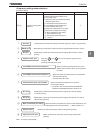
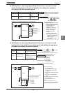
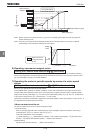
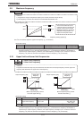
3) Increasing starting torque
Setting of V/f control mode selection RV
RVRV
RV=
(Automatic torque boost)
Detects load current in all speed ranges and automatically adjusts voltage output (torque boost) from inverter.
This gives steady torque for stable runs.
Base frequency voltage 1
XNX
Output voltage
[V]/[%]
Output frequency [Hz]
Base frequency
XN
0
:
The torque
boost rate is
adjusted
automatically.
Note: This control system can oscillate and destabilize runs depending on the load. If that should happen, set V/f
control mode selection RV to (Constant torque characteristics) and increase torque manually.
Ŭ
Motor constant must be set.
The motor constant can be set in any of the following two ways:
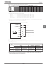
1) Automatic setting
Enter the following information that is indicated on the motor nameplate, and then execute the auto-tuning 1
command (Set H to , and then reset H to .).
<Information indicated on motor nameplate>
XN (Base frequency), XNX (Base frequency voltage), H (Motor rated capacity), H (Motor rated
current), H(Motor rated rotational speed)
Refer to 6.22 selection 2.
2) Manual setting
Set each motor constant manually.
Refer to 6.22 selection 3.