


E6581301
F-25
6
Ŭ
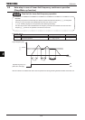
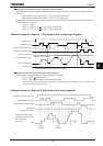
The number of retries will be cleared if the inverter is not tripped for the specified period of time after a successful
retry.
“A successful retry” means that the inverter output frequency reaches the command frequency without causing the
inverter to re-trip.
ŬAt the occurrence of a trip, the rotational speed of the motor is measured and, after the motor is restarted, it’s
speed is regulated to the speed measured.
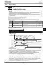
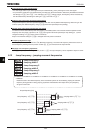
6.14.2 Avoiding overvoltage tripping
H
HH
H :
Overvoltage limit operation
H
HH
H :
Regenerative over-excitation upper
limit
H
HH
H :
Overvoltage limit constant
H
HH
H :
Overvoltage limit operation
level
•
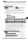
Function
These parameters are used to automatically control the output frequency and prevent the motor from
tripping because of overvoltage due to a rise in the voltage in the DC section during deceleration or
constant speed operation. Note that the deceleration time may be prolonged when the overvoltage limiting
function is activated.
When operating a motor in automatic torque boost mode or vector control mode (
RV
= 2,3,4,7,or 8) at
200V-55kW or more and 400V-90kW or more models, if
H
set 2 or 3,this function same as
H
set 0.
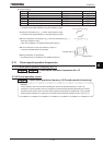
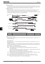
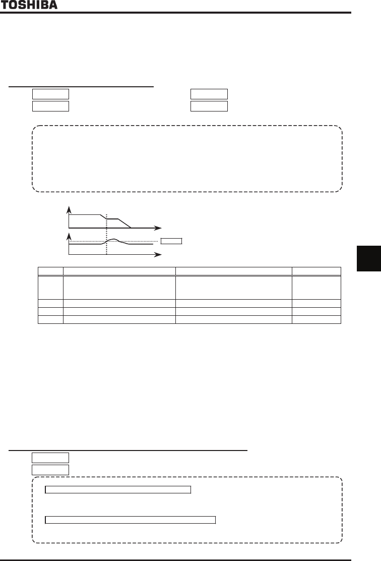
Overvoltage limit operation level
DC
voltage
Output
frequency
H
: Overvoltage stall protection
[Parameter setting]
Title Function Adjustment range Default setting
H
Overvoltage limit operation
:Enabled:Disabled
:Enabled (quick deceleration)
:Enabled (dynamic quick deceleration)
H
Regenerative over-excitation upper limit
~ % [Note]
H
Overvoltage limit constant :Automatic ~ ms
H
Overvoltage limit operation level ~ % [Note]
Note: 100% corresponds to an input voltage of 200V for 200V models or to in an input voltage of 400V for 400V
models.
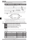
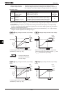
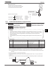
ۻ If H is set to (quick deceleration), the inverter will increase the voltage to the motor (over-excitation
control) to increase the amount of energy consumed by the motor when the voltage reaches the overvoltage
protection level, and therefore the motor can be decelerated more quickly than normal deceleration.
ŬIf H is set to (dynamic quick deceleration), the inverter will increase the voltage to the motor
(over-excitation control) to increase the amount of energy consumed by the motor as soon as the motor begins
to slow down, and therefore the motor can be decelerated still more quickly than quick deceleration.
ŬThe parameter H is used to adjust the maximum energy that the motor consumes during deceleration, and
if the inverter is tripped during deceleration because of an overvoltage, specify a larger value. When H is
set 2 to 3,this function works.
ŬParameter H is able to adjust the filter time constant of the overvoltage limitation.
This parameter is effective at only V/f control mode(RV =0,1,5).
ŬParameter H serves also as a parameter for setting the regenerative braking level (see section 5.19.).
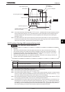
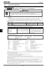
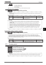
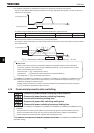
6.14.3 Output voltage adjustment/Supply voltage correction
X
XX
XN
NN
NX
XX
X : Base frequency voltage 1 (output voltage adjustment)
H
HH
H
: Base frequency voltage selection (supply voltage correction)
•
Function
Base frequency voltage 1 (output voltage adjustment)
This parameter is used to set the voltage for the base frequency 1
XN
. It can also be used to prevent the
base frequency over
XNX
from being put out even if the voltage is higher than the voltage set is applied.
(This parameter is operative when
H
is
or
. )
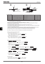
Base frequency voltage selection (correction of supply voltage)
The
H
parameter maintains a constant V/f ratio, even when the input voltage decreases. The torque
during low-speed operation is prevented from decreasing.