


E6581301
H-5
8
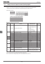
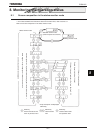
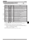
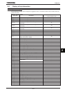
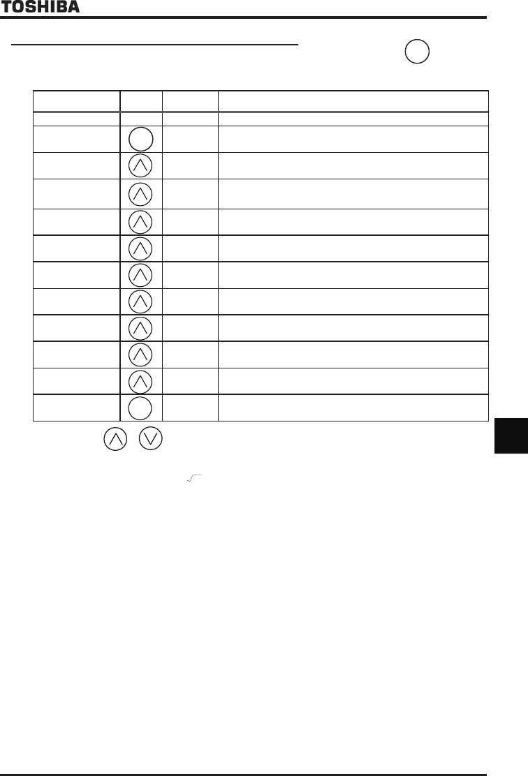
8.2.2 Display of detailed information on a past trip
Details on a past trip (of trips 1 to 4) can be displayed, as shown in the table below, by pressing the key when the
trip record is selected in the status monitor mode.
Unlike the " Monitor display at tripping " in 8.4.2, details on a past trip can be displayed, even after the inverter is turned
off or reset.
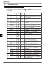
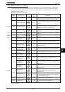
Item displayed
Key
operated
LED display Description
Past trip 1 QE
⇔
Past trip 1 (displayed alternately.)
Continuous trips P
The number of time the same trip occurred in succession is displayed.
(QEC, QEC, QEC, QEN Unit: times)
Output frequency The operation frequency when the trip occurred is displayed.
Status monitor mode
(Rotating direction)
HTH The direction of rotation is displayed. (H:Forward run, T:Reverse run)
Frequency command
value
The operation frequency command value is displayed.
(When H=, Frequency command)
Output current E
The inverter output current (load current) is displayed.
(When H=, Output current)
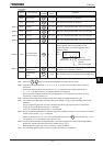
Input voltage (DC
detection)
[
The inverter DC voltage is displayed. (Default setting unit: %)
(When H=, Input voltage) [Note 3]
Output voltage R
The inverter output voltage is displayed. (Default setting unit: %)
(When H=, output voltage)
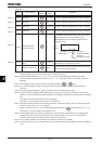
Input terminal
information
KKKKKKKK
The ON/OFF status of each of the control signal input terminals (F, R,
ST, RES, S1, S2, S3, RR/S4) is displayed in bits.
Output terminal
information
The ON/OFF status of each of the control signal output terminals
(OUT1, OUT2, FL) is displayed in bits.
Cumulative operation
time
V
The cumulative operation time when the trip occurred is displayed.
(0.01=1 hour, 1.00=100 hours)
Past trip 1 QE
⇔
Press this key to return to past trip 1.
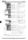
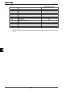
Note 1: Press the or key to change items displayed in the status monitor mode.
Note 2: You can switch between % and A (ampere)/V (volt), using the parameter FURW (current/voltage unit
selection).
Note 3: The input voltage displayed is 1/
2
times as large as the rectified DC input voltage.
Note 4: The number of bars displayed varies depending on the setting of H (logic output/pulse train output
selection). The bar representing the OUT1 terminal is displayed only when logic output function is assigned to it.
If H= :The bar representing OUT1 is displayed.
If H= :The bar representing OUT1 is not displayed.
Note 5: If there is no trip record, PGTT is displayed.
Note 6: The cumulative operation time increments only when the machine is in operation.
ENT
ENT
[Note 5]
[Note 1]
MODE
[Note 6]
[Note 4]
[Note 2]
[Note 2]
[Note 3]
[Note 2]