


E6581301
C-2
3
3.1 Setting/monitor modes
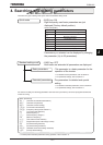
The VF-AS1 has the following three setting/monitor modes.
Standard monitor mode The standard inverter mode. This mode is enabled
when inverter power goes on.
Setting monitor mode The mode for setting inverter parameters.
How to set parameters, refer to Section 4. 1.
This mode is divided into two modes according to the parameter readout mode
selected.
Quick mode :Eight frequently used basic parameters are just displayed.
The maximum 32 parameters that you select by
yourselves are displayed.
Standard setting mode :Both basic and extended all parameters are displayed.
Status monitor mode The mode for monitoring all inverter status.
Allows monitoring of set frequencies, output current/voltage and terminal
information.
Refer to Section 8.
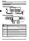
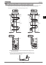
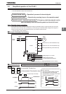
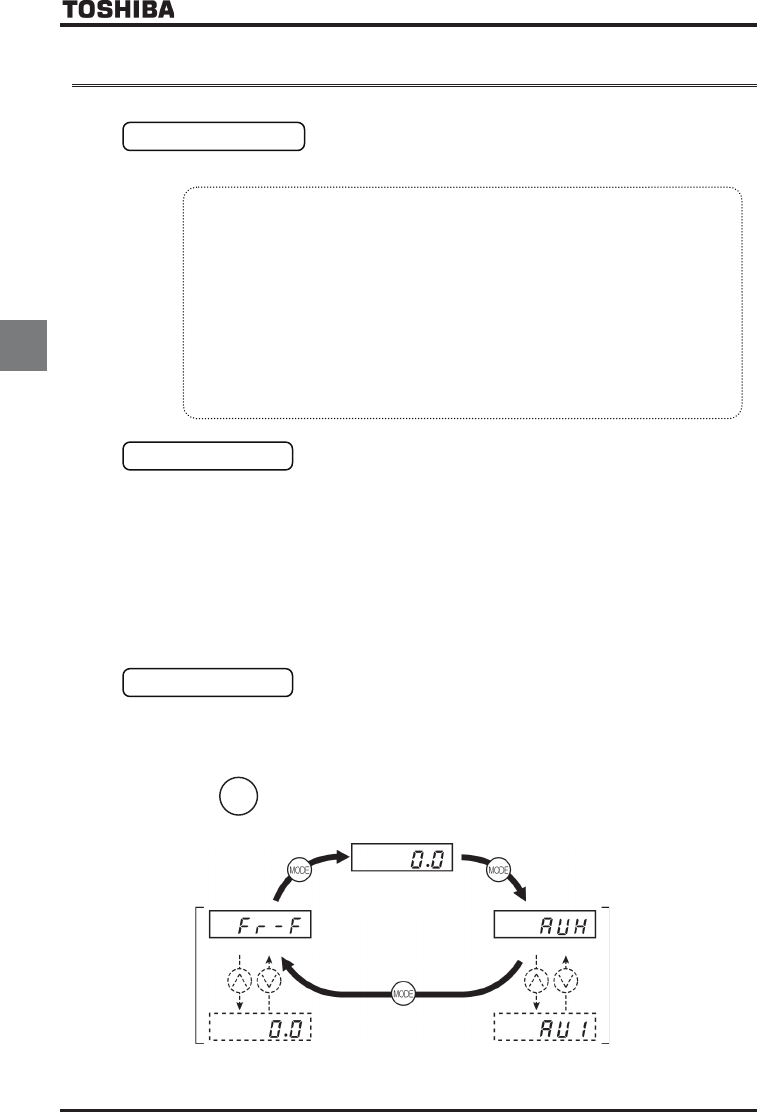
Pressing the key
MODE
will move the inverter through each of the modes.
Status monitor mode
Standard monitor mode
(when the power is turned on)
Setting monitor mode
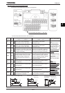
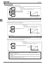
This mode is for monitoring the output frequency and setting the frequency reference value. If also
displays information about status alarms during running and trips.
• Setting frequency reference values Refer to Section 3.2.2.
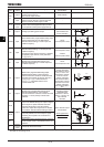
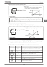
• Status alarm
If there is an error in the inverter, the alarm signal and the frequency will flash alternately in
the LED display.
E: When a current flows at or higher than the overcurrent stall prevention level.
R: When a voltage is generated at or higher than the over voltage stall prevention level.
N: When the cumulative amount of overload reaches 50% or more of the overload trip
value.
J: When temperature inside the inverter rises above overheating protection alarm level
(about 95°C)
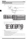
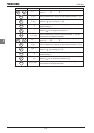
How to search and set
parameters
Refer to Section 4.1.
Monitoring of
operation status
Refer to
Section 8.1.