


E6581301
E-10
5
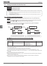
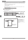
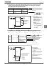
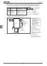
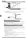
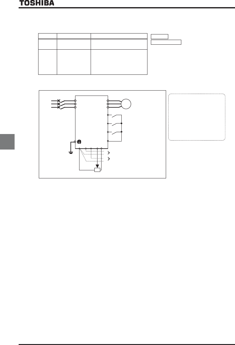
4) Setting the run, stop and operation frequencies (forward run, reverse
run and coast stop) by means of external signals (default setting)
Title Function Example of setting
Run/stop :ON/OFF of terminals F-CC/R-CC
Speed command :External signal input
(1) VI/II terminal: 0~+10Vdc
(0~+5Vdc) or
4(0)~20mAdc
(2) RR/S4 terminal: Potentiometer
0~+10Vdc (0~+5Vdc)
(3) RX terminal: 0~±10Vdc (0~±5Vdc)
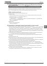
EOQF
Command mode
selection
:(Terminal input)
HOQF
Frequency
setting mode
selection 1
(VI/II (voltage/current input) )
(RR/S4
(potentiometer/voltage
input) )
(RX (voltage input) )
Motor
IM
R/L1
Power
supply
S/L2
T/L3
U/T1
V/T2
W/T3
(1) 0~+10Vdc
(0~+5Vdc)
or 4(0)~20mAdc
(3) 0~±10Vdc
(0~±5Vdc)
(2) External potentiometer
-
-
+
+
F
R
ST
CC
ON:Forward run,
OFF:Deceleration stop
ON:Reverse run,
OFF:Deceleration stop
ON:Standby,
OFF:Coast stop
* Other speed setting
: 2-wire RS485 input
: 4-wire RS485 input enabled
: Communication option input enabled
*
:
Optional
AI1 (Differential current
input)
*
:
Optional
AI2 (voltage/current input)
*
:
Motor operated pot mop setting
: RP pulse input
*
: High-speed pulse input
*
: -
* Commands marked with * are
optional. Refer to Instruction Manual
of options described in Section 10.
CCA RX
VI/II
RR/S4
PP
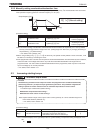
Inverter
Ŭ
The inverter is
factory-
configured so that,
if F and R are turned on at
the same time, the
inverter will stop
operation. If necessary,
the direction of rotation
can be reversed by
changing parameter
settings.
Refer to Section 6.2.
1
.
«
Example of a connection diagram: SW1 set to sink logic
»