


E6581301
A-18
1
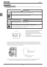
High-speed operation at and above 50Hz/60Hz (rated frequency)
Operating at frequencies greater than 50Hz/60Hz will increase noise and vibration. There is also a possibility that
such operation will exceed the motor's mechanical strength under these conditions and the bearing limits. You
should verify with the motor's manufacturer operating.
Method of lubricating load mechanisms
Operating an oil-lubricated reduction gear and gear motor in the low-speed areas will worsen the lubricating effect.
Check with the manufacturer to find out about operable speed range.
Low loads and low inertia loads
The motor may demonstrate instability such as abnormal vibrations or overcurrent trips at light loads of 50% or
under of the rated load, or when the load's moment of inertia is extremely small. If that happens reduce the carrier
frequency.
Occurrence of instability
Unstable phenomena may occur under the load and motor combinations shown below.
• Combined with a motor that exceeds applicable motor ratings recommended for the inverter
• Combined with special motors
To deal with the above lower the settings of inverter carrier frequency. (When performing vector control, set the
carrier frequency at 2kHz or more. If the carrier frequency is set below 2kHz, it will be automatically corrected to
2kHz by the inverter.)
• Combined with couplings between load devices and motors with high backlash
In this case, set the S-pattern acceleration/deceleration function and adjust the response time inertial moment
setting during vector control or switch to V/f control (
RV
=
Q
).
• Combined with loads that have sharp fluctuations in rotation such as piston movements
In this case, adjust the response time inertial moment setting during vector control or switch to V/f control (
RV
=
Q
).
If it is operated in vector control mode (For torque control mode), only a motor whose capacity is same as inverter
standard or 1 size smaller should applied.
Braking a motor when power supply is lost
A motor with its power cut off goes into freewheel, and does not stop immediately. To stop the motor quickly as
soon as the power is cut off install an auxiliary brake. There are different kinds of brake devices, both electrical and
mechanical. Select the brake that is best for the system.
Loads that generate negative torque
When combined with loads that generate negative torque the protection for overvoltage and overcurrent on the
inverter will go into operation and may cause a trip. For this kind of situation, you must install a dynamic braking
resistor, etc. that complies with the load conditions.
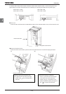
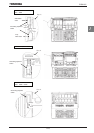
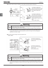
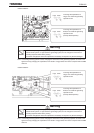
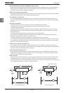
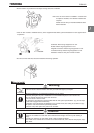
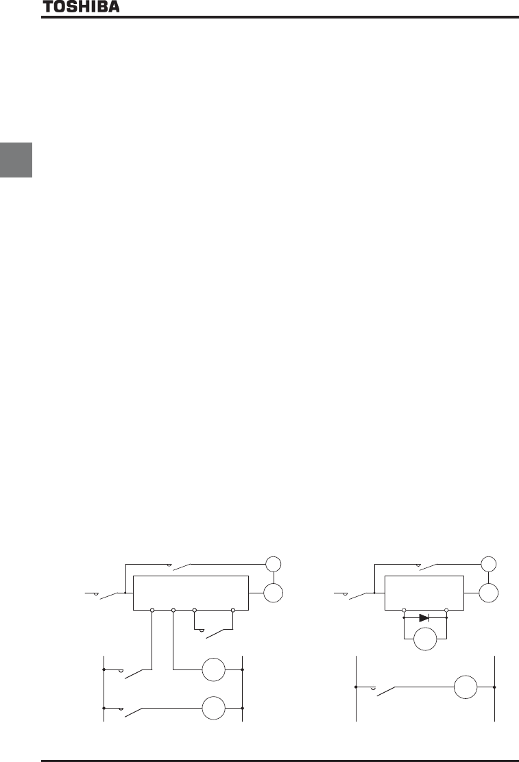
Motor with brake
If a brake motor is used with the braking circuit connected to the output terminals of the inverter, the brake cannot
be released because of a voltage drop at startup. Therefore, when using the inverter along with a brake motor,
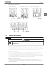
connect the braking circuit to the power supply side of the inverter, as shown in the figure below. In most cases, the
use of a brake motor causes an increase in noise at low-speed.
B
IM
LOW
OUT1
P24
Three-
phase
power
supply
MC
2
MC3
MC2
MC1
MC2
B
IM
MC3
MC1
MC3
FLB
FLC
ST
CC
Three-ph
ase
power
supply
LOW
(Non-exciting brake)
(Non-exciting brake)
MC1
MC2
Circuit configuration 1 Circuit configuration 2