


E6581301
I-6
9
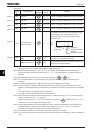
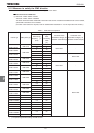
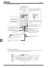
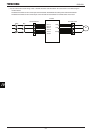
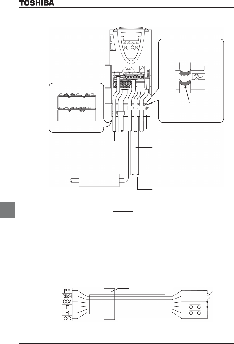
[Ex. Countermeasure - inverter wiring]
EMC FILTER
Peel off the outer sheath of the cable
and fix the shielded part with a metal
saddle.
Strip and earth the shielded cable,
following the example shown in
Fig.
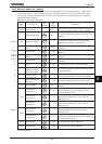
Control wiring (Shielded cabless)
Relay contact output FLA, FLB, FLC
Control wiring (Shielded cabless)
Analog input VI/II, RR/S4, PP, CCA
Analog output FM, AM, CCA
PG feedback signal line (Shielded cabless)
Power supply wiring (Shielded cabless)
R/L1, S/L2, T/L3
Motor wiring (Shielded cabless)
U/T1, V/T2, W/T3
Braking resistor wiring (Shielded cabless)
PA/+, PB
EMC
plate
(Refer to Table 2.)
4-wire RS485 communication line
(Shielded cabless)
Control wiring (Shielded cabless)
Logic input/output +SU, F, R, S1
᳸
S3, RES,
ST, NO, P24/PLC, OUT1,
OUT2, CC
Fig. 2
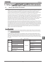
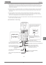
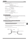
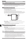
[Operation with external signals]
When using signals from an external control device to operate the inverter, take the measures shown in Figure 3.
Ex.) When using the potentiometer and forward run/reverse run terminals
Ferrite core 1
Shielded cable or [Note 1]
Fig. 3