


K-1
E6581301
11
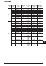
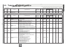
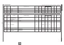
11. Table of parameters
1. User parameter *3 Sensorless vector/vector with sensor (Ɣ:Effective, -:Ineffective)
Title
Communi
cation
No.
Function Adjustment range
Minimum
setting unit
(Panel/Communi
cation)
Default
setting
Write during
running
Vector contro
l
PM
control
*2
V/f
*1
Reference
Speed
control
Torque
control
HE -
Operation
frequency of
operation panel
NN~HJ Hz 0.1/0.01 0 Enabled Ɣ/Ɣ Ɣ/Ɣ Ɣ Ɣ 3. 2
*1: V/f : Any setting of RV=,,*2: PM control : RV= setting *3: Sensorless vector : Any setting of RV=,, / Vector with sensor : Any setting of RV=,
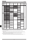
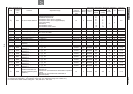
2. Basic parameter [1/4] Sensorless vector/vector with sensor (Ɣ:Effective, -:Ineffective)
Title
Communi
cation
No.
Function Adjustment range
Minimum
setting unit
(Panel/Communi
cation)
Default
setting
Write during
running
Vector control
PM
control
V/f
Reference
Speed
control
Torque
control
CWJ
-
History function
1/1
-
-
Ɣ
/
Ɣ
Ɣ
/
Ɣ
Ɣ
Ɣ
5. 1
CW
0000
Automatic
acceleration/deceleration
0:Disabled
1:Automatic setting
2:Automatic setting (during acceleration only)
1/1 0 Disabled Ɣ/Ɣ - Ɣ Ɣ 5. 2
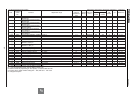
CW
0001 Automatic torque boost
0:Disabled
1:Automatic torque boost + auto-tuning 1
2:
Sensorless vector control 1
+ auto
-
tuning
1
1/1 0 Disabled Ɣ/Ɣ - Ɣ Ɣ 5. 3
CW
0040
Automatic function
setting
0:Disabled
1:Frequency setting by means of voltage
2:Frequency setting by means of current
3:Voltage/current switching from external terminal
4: Frequency setting on operation panel and operation by
means of terminals
5: Frequency setting and operation on operation panel
1/1 0 Disabled Ɣ/Ɣ Ɣ/Ɣ Ɣ Ɣ 5. 4
EOQF
0003
Command mode
selection
0:Terminal input enabled
1:Operation panel input enabled (including LED/LCD
option input)
2:2-wire RS485 communication input
3:4-wireRS485 communication input
4:Communication option input
1/1 0 Disabled Ɣ/Ɣ Ɣ/Ɣ Ɣ Ɣ 5. 5
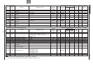
HOQF
0004
Frequency setting mode
selection 1
1:VI/II (voltage/current input)
2:RR/S4 (potentiometer/voltage input)
3:RX (voltage input)
4:Operation panel input enabled (including LED/LCD
option input)
5:2-wire RS485 communication input
6:4-wire RS485 communication input
7:Communication option input
8:Optional AI1 (differential current input)
9:Optional AI2 (voltage/current input)
10:Motor operated pot mop setting
11:Optional RP pulse input
12:Optional high-speed pulse input
13:
-
(
Unsupporte
d option
)
1/1 2 Disabled Ɣ/Ɣ - Ɣ Ɣ 5. 5