


E6581301
F-85
6
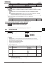
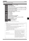
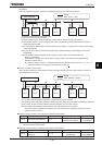
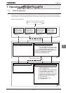
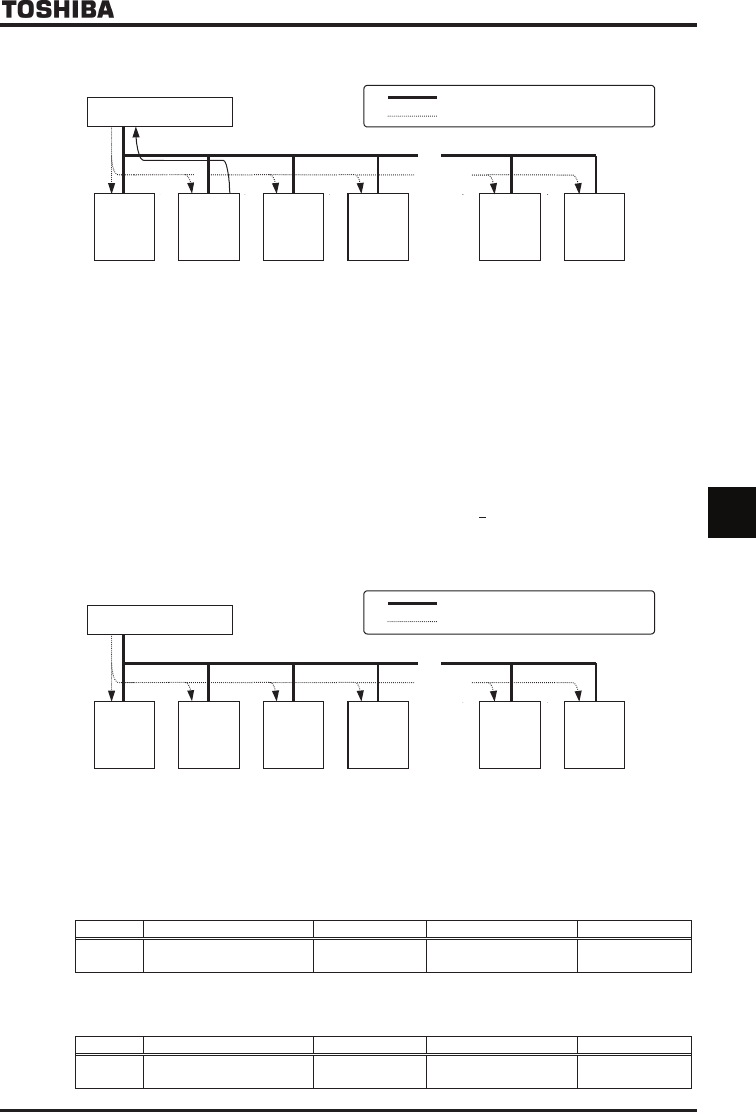
<Broadcast>
When an operation frequency command is broadcasted from the host computer to inverters
INV
No.29
INV
No.30
~
~
: Wiring
: Data (host
→
INV)
INV
No.03
INV
No.02
INV
No.00
Ŭ Ŭ Ŭ ŬŬ
INV
No.01
Host computer
Ŭ: Use the terminal board to branch the cable.
(1) Data is sent from the host computer.
(2) Data from the computer is received at each inverter and the inverter numbers are checked.
(3) Data with an asterisk (*) in the inverter number position is taken as broadcast data and the command is
deciphered and executed.
(4) To avoid collisions between data, only the inverter with the asterisk (*) replaced with a zero (0) returns data
to the host computer.
(5) As a result, all inverters connected are operated at the operation frequency specified by the command
broadcasted.
Note: If an inverter number is assigned to each group of inverters, data can be broadcasted on a
group-by-group basis.
(This function is usable only in ASCII mode. For binary mode, see Instruction Manual (E6581315)
specified in Section 6.42.)
Ex.) When the inverter number *1 is specified, data is broadcasted to inverters Nos. 01, 11, 21, 31, ... 91.
At that time, data is returned by the inverter bearing number 01.
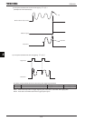
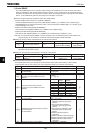
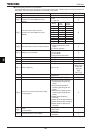
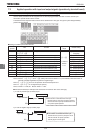
■ Inverter-to-inverter communication
When all slave inverters are connected they operat at the same frequency as the master inverter (no setting of
point frequencies in this case)
Master inverter
INV
No.29
INV
No.30
~
~
: Wiring
: Data (Master
→
Slave)
INV
No.03
INV
No.02
INV
No.01
INV
No.00
Ŭ Ŭ Ŭ ŬŬ
Ŭ: Use the terminal board to branch the cable.
(1) The master inverter transmits frequency command data to its slave inverters.
(2) The slave inverter calculate a frequency reference from the data received and save the frequency calculated.
(3) As a result, all slave inverters operate at the same frequency as the master inverter.
Note: The master inverter always sends frequency command data to its slave inverters.
The slave inverters are always on standby so that they can receive an frequency command from the
master inverter at anytime.
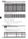
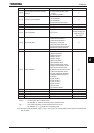
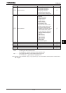
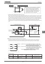
■ Setting for issuing run/stop commands from an external control device
Title Function Adjustment range Default setting Example of setting
EOQF Command mode selection ~
(Terminal input enabled)
(4-wire RS485)
Note: When parameter H (setting for communications between inverters) is used, the setting EOQF=
cannot be used for slave inverters.
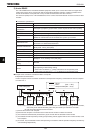
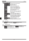
■ Setting for issuing speed commands from an external control device
Title Function Adjustment range Default setting Example of setting
HOQF
Frequency setting mode
selection 1
~
(RR/S4 input)
(4-wire RS485)