


E6581301
H-12
8
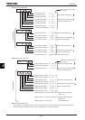
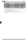
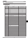
(Continued)
Commun
ication
No.
Item displayed
Key
operated
LED
display
Description
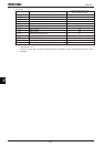
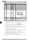
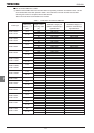
FE10 Past trip 1
E
⇔
Past trip 1 (displayed alternately at 0.5-sec. intervals)
FE11 Past trip 2 J
⇔
Past trip 2 (displayed alternately at 0.5-sec. intervals)
FE12 Past trip 3 R
⇔
Past trip 3 (displayed alternately at 0.5-sec. intervals)
FE13 Past trip 4 PGTT
⇔
Past trip 4 (displayed alternately at 0.5-sec. intervals)
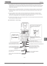
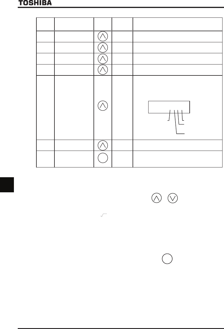
FE79
Part replacement
alarm information
O___K
The ON/OFF status of each of the cooling fan, circuit
board capacitor, main circuit capacitor or part
replacement alarm of cumulative operation time is
displayed in bits.
ON:
OFF: _
FE14
Cumulative operation
time
V
The cumulative operation time is displayed.
(Indication of 0.1 represents 10 hours.)
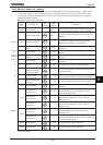
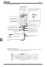
- Default display mode
×2
R
Status monitor mode (The code blinks if a trip occurs.)
Reverts to the first trip indication.
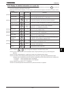
Note 1: If trouble occurs while the CPU is being initialized after the inverter is turned on or reset, the trip record
retaining function does not record it but displays a status monitor item.
Note 2: Contents of status indications of *1, *2, *3, *4, *5, *6, *7, and *8 can be selected from 44 kinds of information.
Contents of status indications that are set up at H~H (status monitor 1 to 8 display mode) are
displayed.
Note 3: Items displayed when a trip occurs can be changed by pressing or key.
Note 4: You can switch between % and A (ampere)/V (volt), using the parameter FURW (current/voltage unit
selection).
Note 5: The input voltage displayed is 1/
2
times as large as the rectified DC input voltage.
Note 6: The number of bars displayed varies depending on the setting of H (logic output/pulse train output
selection). The bar representing the OUT-NO terminal is displayed only when logic output function is assigned
to it.
If H=:The bar representing OUT-NO is displayed.
If H=:The bar representing OUT-NO is not displayed.
Note 7: Past rip records are displayed in the following sequence: 1 (latest trip record)
⇔
2
⇔
3
⇔
4 (oldest trip record).
If there is no trip record, PGTT is displayed.
Details on past trip record 1, 2, 3 or 4 can be displayed by pressing the key when past trip 1, 2, 3 or 4
is displayed.
For more details, refer to Section 8.2.2.
Note 8: The time elapsed before an end of part replacement alarm is issued is calculated from the average yearly
ambient temperature, operation time and load current entered using H, and it is no more than an
estimation, and therefore it should be used for reference purposes only.
Note 9: The cumulative operation time increments only when the machine is in operation.
Note 10: At the occurrence of a trip, maximum values are not always recorded and displayed for reasons of detecting
time.
ENT
[Note 7]
[Note 7]
[Note 7]
O___K
Cooling fan
Cumulative
operation time
Control circuit board
capacitor
Main circuit capacitor
MODE
[Note 9]
[Note 7]
[Note 8]