


E6581301
F-51
6
6.28 Fine adjustment of frequency setting signal
H
HH
H
: VI/II input bias
H
HH
H
: VI/II input gain
H
HH
H
: RR/S4 input bias
H
HH
H
: RR/S4 input gain
H
HH
H : RX input bias
H
HH
H : RX input gain
H
HH
H : Optional AI1 input bias
H
HH
H : Optional AI1 input gain
H
HH
H : Optional AI2 input bias
H
HH
H : Optional AI2 input gain
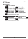
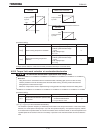
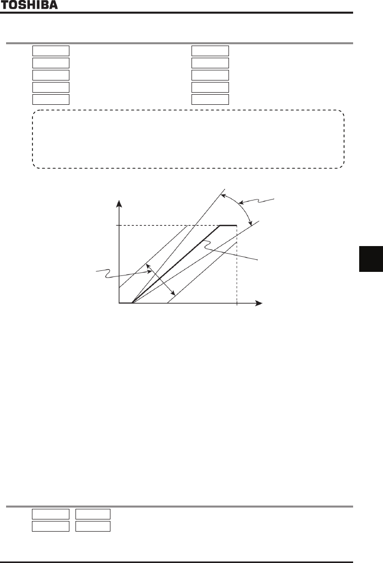
The figure below shows the characteristic of the frequency setting signal input through the analog input terminal and
that of the output frequency.
Output frequency [Hz]
Maximum frequency
H
,
H
H
,
H
H
0
H
,
H
,
H
H
,
H
Factory default setting
Large
Small
Small
Large
0
Ჟ
100
Ჟ
0V 10Vdc
4mA 20mAdc
Frequency setting signal (Analog input terminal)
★Bias adjustment of analog input terminals (H, H, H, H, H)
To give leeway, the inverter is factory-adjusted by default so that it will not produce an output until a certain amount
of voltage is applied to the analog input terminals.
To reduce leeway, decrease the bias of the analog terminal in use.
Note that specifying a too large value may cause an output frequency to be output, even though the operation
frequency is 0 (zero) Hz.
★Gain adjustment of analog input terminals (H, H, H, H, H)
The inverter is factory-adjusted by default so that the operation frequency can reach the maximum frequency, even
though the voltage and current to the analog input terminals are below the maximum levels.
To make an adjustment so that the frequency reaches its peak value at the maximum voltage and current, decrease
the gain of the analog terminal in use.
Note that specifying a too small value may cause the operation frequency not to reach the maximum frequency,
even though the maximum voltage and current are applied.
6.29 Operating a synchronous motor
H
HH
H , H
HH
H : PM motor constant 1
H
HH
H , H
HH
H : Step-out detection current level/ detection time
This parameter is used only when the inverter is used with a synchronous motor. If you intend to use your inverter
with a synchronous motor, contact your Toshiba distributor.
• Function
These parameters are used to fine adjust the relation between the frequency setting signal input through
the analog input terminal and the output frequency.
Use these parameters to make fine adjustments after making rough adjustments using the parameters
H~H
.