


E6581301
J-10
10
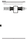
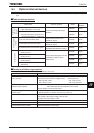
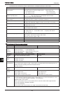
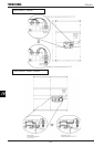
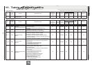
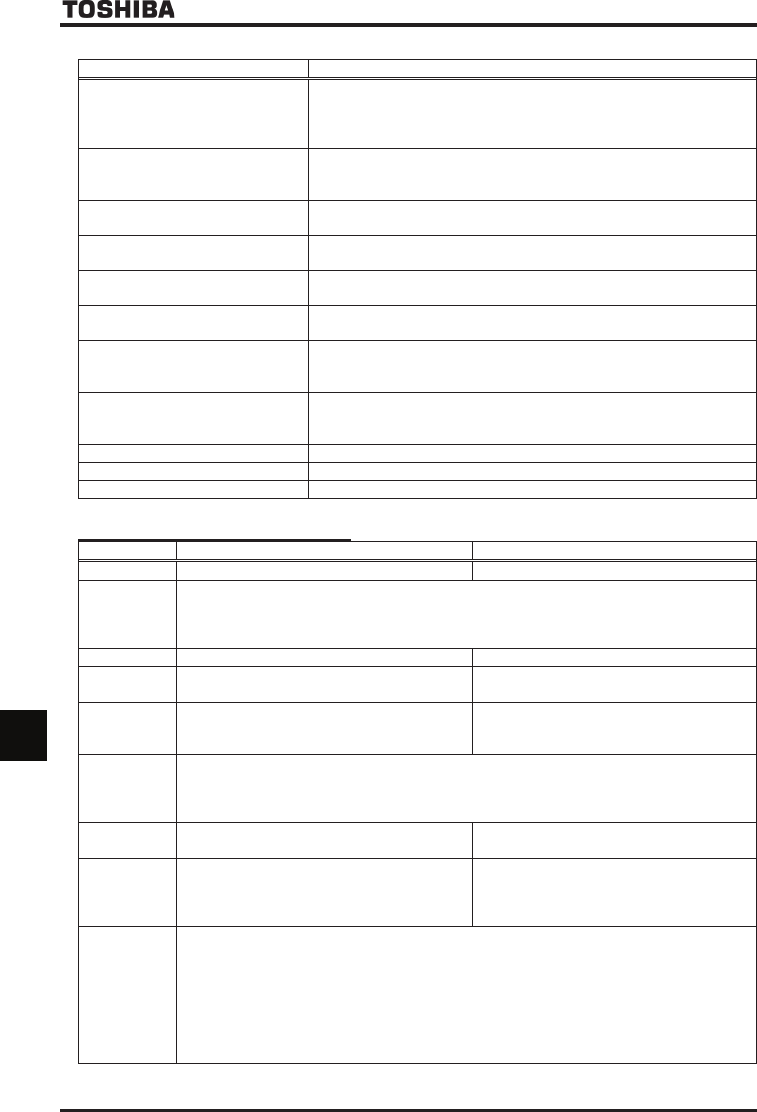
(2) Expansion I/O card2 option (Function of optional card 1 + Analogue input/output + Pulse input)
Function Description
Multifunction programmable contact
input (4 points)
No-voltage contact input (24Vdc-5mA or less)
Sink logic input (at a common voltage of 24V) Source logic input
ON: Less than 10Vdc ON: 11Vdc or more
OFF: 16Vdc or more OFF: Less than 5Vdc
Multifunction programmable open
collector output (2 points)
Driving current: Max. 50mA when an external power source is used
Max. 20mA when the internal power source is used
Driving voltage: 12V (min) to 30V (max)
Multifunction programmable relay
contact output
1C contact configuration
250Vac-2A (cosφ=1), 250Vac-1A (cosφ=0.4), 30Vdc-1A
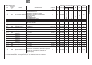
Differential current input Current input: 20mA or less
Voltage input: Differential voltages 5V or less, -10V or more, +10V or less
Analog input Current input: 20mA or less
Voltage input: 0V to 10V
Monitor output Voltage output: -10V to 10V, 0V to 10V
Current output: 0mA to 20mA
Pulse train input Input pulse specifications
Voltage: Max. 5V Current: Max. 15mA Frequency: Max. 30kHz
Duty: 50±10%
External thermal trip input Resistance between TH+ and TH-
Error: Approx. 70 or less or approx. 3k or more
Recovery from error: Approx. 1.6k
24V power output 24Vdc - 60mA max
-10V power output -10Vdc -10mA
Contact input common terminal Common terminals for contact input
■
■■
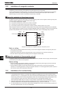
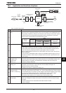
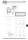
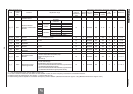
■ Functions of Plug-in type options
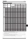
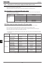
PG feedback option (6) (7) (8) PG feedback option (9)
Model VEC004Z, VEC005Z, VEC006Z VEC007Z
Sensor vector
control
operation
Speed control operation: Zero-speed - 150% torque
Speed control range: 1:1000 (1000ppr PG)
Torque control operation: Torque control accuracy ±10%
Torque control range: -100% to +100%
PG method Complementary method, open collector method Line drive method
PG cable
length
Max. 100m (complementary method) Max. 30m
PG supply
power
VEC004Z: 12V-160mA
VEC005Z: 15V-150mA
VEC006Z: 24V-90mA
5V-160mA
Maximum pulse
input frequency
300kHz or less
* If a two-phase open collector is used, a study needs to be made to determine the derating factor. For
details, refer to the operating manual for the optional device.
Pulse duty: 50±10%
Pulse input
voltage
12Vdc to 24Vdc Line driver (LTC485 or equivalent)
Recommended
encoder
Manufacturer: Sumtak Corporation
Model: IRS360 series
Supply voltage: 10.8 to 26.4V
Output method: Complementary output
Manufacturer: Sumtak Corporation
Model: IRS320 series
Supply voltage: 5V
Output method: Line driver method
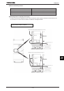
Wiring of
encoder
Cable type: Twisted-pair shielded cable
Conductor resistance: Conductor resistance (/m) x cable length (m) x 2 x current consumption (A) < V
D
(V)
V
D
(V): 1.0V (VEC004Z, VEC005Z, VEC006Z), 0.3V (VEC007Z)
Applicable cable: 0.2 to 0.75mm
2
* When a power cable 0.2 mm
2
in cross sectional area is used, the encoder cable length should be:
Max. 30m (VEC004Z, VEC005Z, VEC006Z)
Max. 10m (VEC007Z)
Recommended cable: Kuramo Electric KVC-36SB, Furukawa Electric ROVV-SB