


E6581301
F-32
6
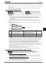
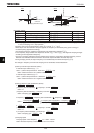
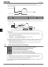
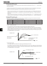
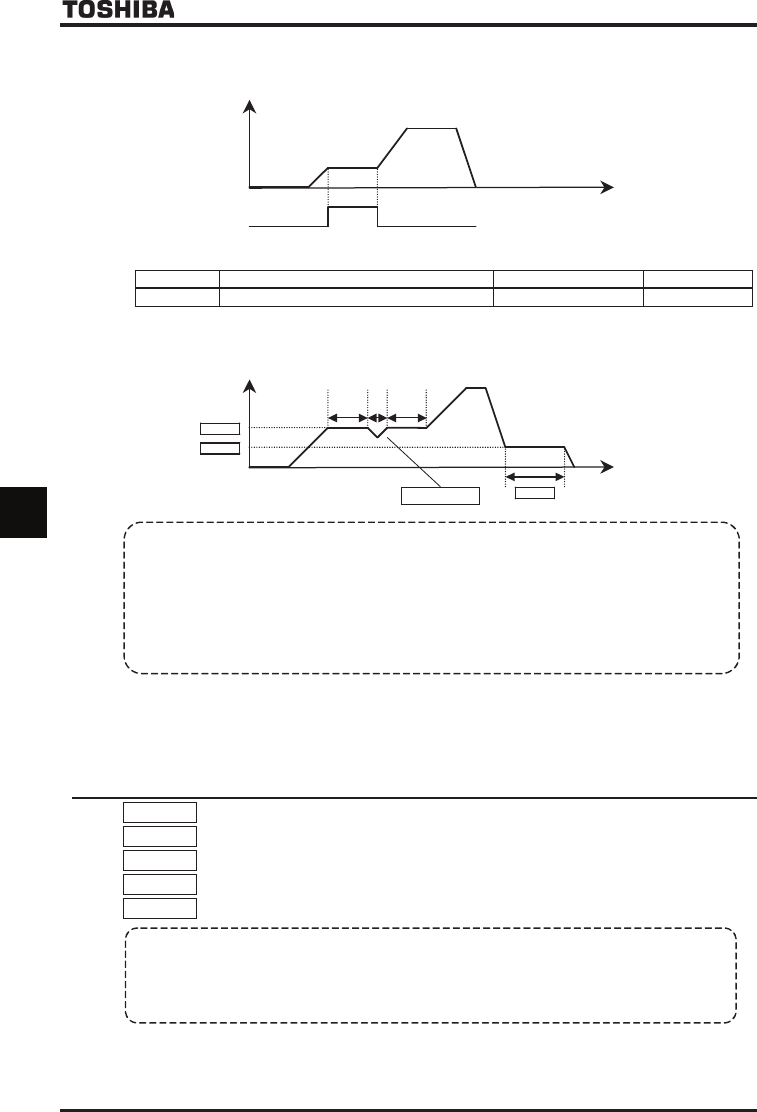
2) To suspend acceleration or deceleration by means of a signal from an external control device
Set for the desired external signal input terminal. As long as ON signals are inputted, the motor continues to
rotate at a constant speed.
Output frequency [Hz]
Time [s]
Terminal board input
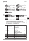
Ex.) When using the RR/S4 terminal as the acceleration/deceleration suspend terminal
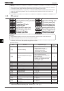
Title Function Adjustment range
Example of setting
H Input terminal function selection 8 (RR/S4) ~
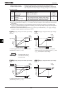
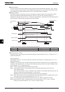
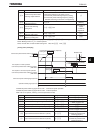
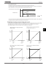
■ If the stall control function is activated during constant-speed rotation
The frequency drops momentarily as a result of stall control, but the time for which the frequency drops is included
in the suspend time.
Output frequency [Hz]
H
H
Time [s]
H
Stall
t1 ts t2
H (Momentary acceleration (deceleration) suspend time) = (t1 + t2 + ts)
Stall control
Refers to the inverter’s function of automatically changing the operation frequency when it detects an
overcurrent, overload or overvoltage. Using the following parameters, you can specify the way, the stall
control is performed for each kind of stall.
Overcurrent stall :
H
(Stall prevention level 1)
Overload stall :
QNO
(Electronic thermal protection characteristic selection)
Overvoltage stall :
H
(Overvoltage limit operation)
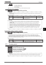
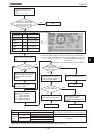
Note: Setting the frequency command at the same frequency as the acceleration suspend frequency (H)
disables the acceleration suspend function.
Similarly, setting the frequency command at the same frequency as the deceleration suspend frequency
(H) disables the deceleration suspend function.
6.19
Commercial power/inverter switching
H
HH
H : Commercial power/inverter switching output selection
H
HH
H : Commercial power/inverter switching frequency
H
HH
H : Inverter-side switching waiting time
H
HH
H : Commercial power-side switching waiting time
H
HH
H : Commercial power switching frequency holding time
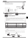
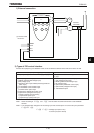
• Function
These parameters are used to specify whether to send a switching signal to an external sequencer (such as
an MC) in the event that the inverter trips. The use of an input signal makes it possible to switch between
inverter operation and commercial power operation without stopping the motor.
For details, see Instruction Manual (E6581364) specified in Section 6.42.
[Parameter setting]