


E6581301
B-3
2
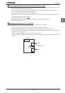
• Refer to the table in Section 10.1 for wire sizes.
• The length of the main circuit wire in Section 10.1 should be no longer than 30m. If the wire is longer than 30m, the
wire size (diameter) must be increased.
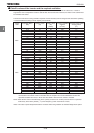
• Tighten the screws on the terminal board to specified torque.
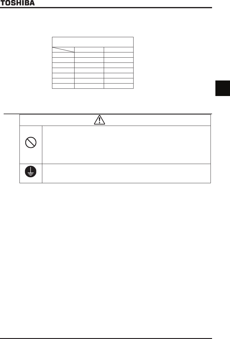
Recommended tightening torque for screws on
the terminal board
N·m Ib·ins
M3 0.6 5.3
M4 1.4 12.4
M5 3.0 26.6
M6 5.4 47.8
M8 12.0 106
M10 24.0 212
M12 41.0 360
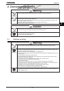
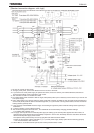
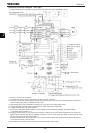
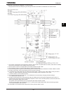
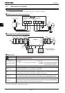
2.2 Standard connections
Warning
Prohibited
• Do not connect input power to the output (motor side) terminals (U/T1, V/T2, W/T3).
Connecting input power to the output could destroy the inverter or cause a fire.
• Do not connect a regenerative braking resistor to any DC terminal (between PA/+ and PC/-, or
between PO and PC/-).
If a braking resistor is connected by mistake, it may overheat extremely and cause a fire.
Connect resistors as directed in the instructions for Section 5.19.
• Within 15 minutes after turning off input power, do not touch wires of devices (MCCB) connected to
the input side of the inverter.
That could result in electric shock.
Be Grounded
• Ground must be connected securely.
If the ground is not securely connected, it could lead to electric shock or fire when a malfunction or
current leak occurs.