


E6581301
M-1
13
13.
Before making a service call
- Trip information and remedies
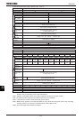
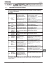
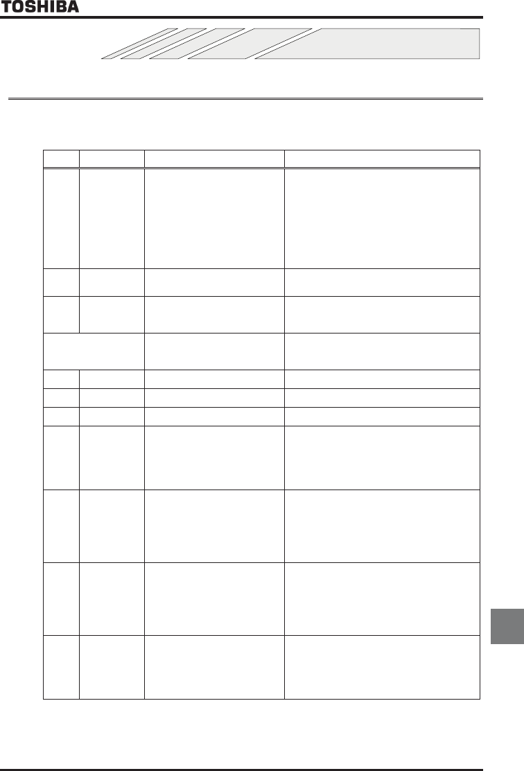
13.1 Trip causes/warnings and remedies
When a problem arises, diagnose it in accordance with the following table.
If it is found that replacement of parts is required or the problem cannot be solved by any remedy described in the
table, contact your Toshiba distributor.
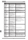
[Trip information]
Error
code
Description Possible causes Remedies
QE
*QER
Overcurrent
during
acceleration
•
The acceleration time
CEE
is too short.
•The V/f setting is improper.
•A restart signal is input to the
rotating motor after a momentary
stop, etc.
•A special motor (e.g. motor with a
small impedance) is used.
•
Manual torque boost value (
XD
) is large.
•There is possibility of
gr
ound fault.
•Increase the acceleration time
CEE
.
•Check the V/f parameter setting.
•Use WX(Auto-restart) and WXE (Regenerative
power ride-though control).
•Increase the carrier frequency EH.
•Decrease XD setting value.
•Decrease H (stall prevention level) to 130
as a guide.
•Increase EH (carrier frequency) setting value if it
is set at lower value (2kHz or less).
•Check the cable and the motor for ground faults.
QE
*QER
Overcurrent
during
deceleration
•The deceleration time
FGE
is too
short. (in deceleration)
•There is possibility of
g
round fault.
•Increase the deceleration time
FGE
.
•Check the cable and the motor for ground faults.
QE
*QER
Overcurrent
during fixed
speed
•The lo
ad fluctuates abruptly.
•The load is in an abnormal
condition.
•There is possibility of
g
round fault.
•Reduce the load fluctuation.
•Check the load (operated machine).
•Check the cable and the motor for ground faults.
[Note]
QER
,
QER
,
QER originate from
causes other than those
mentioned above.
•
A main circuit elements is defective.
•Overheat protection is activated.
•Contact your Toshiba distributor.
•Check operation of cooling fan.
•Check cooling fan control mode parameter
H.
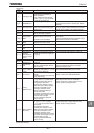
*QEC
U
-
phase
arm
sh
ort
-
circuit
•A main circuit elements is defective
(U
-
phase).
•Contact your Toshiba distributor.
*QEC
V
-
phase
arm
short-circuit
•A main circuit elements is defective
(V-phase).
•Contact your Toshiba distributor.
*QEC
W
-
phase
arm
short
-
circuit
•A main ci
rcuit elements is defective
(W
-
phase).
•Contact your Toshiba distributor.
QEN
Loaded side
overcurrent at
start time
•The insulation of the output main
circuit or motor is defective.
•The motor has too small
impedance.
•The drive circuit board in the
inverter was damaged.
•Check the cables and wires for defective
insulation.
•Selection of short circuit detection at starting
parameter H.
•If this error message appears when a motor is not
connected to the inverter, the inverter itself may
be faulty, so
c
on
tact your Toshiba distributor.
QET
Dynamic braking
element
overcurrent
(200V-55kW or
larger,
400V-90kW or
larger)
•
PB
-
P
A
/+
circuit is shorted.
•A resistor with resistance smaller
than the minimum allowable
resistance is connected.
•Parameter RD was set to or
without connecting regenerative
brake or with wire disconnected
(with dynamic braking).
•Check the impedance wiring for the resistor, etc.
•Contact your Toshiba distributor.
•Check if regenerative brake is connected.
•If regenerative brake is not necessary, set
parameter RD to .
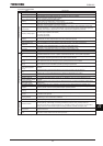
QJ
Overheating
•The cooling fan does not rotate.
•The ambient temperature is too
high.
•The vent is blocked up.
•A heat generating device is
installed close to the inverter.
•The thermistor in the unit is
disconnected.
•R
estart the operation by resetting the inverter
after it has cooled down enough.
•The fan requires replacement if it does not rotate
during operation.
•Secure sufficient space around the inverter.
•Do not place any heat generating device near the
inverter.
•Contact your Toshiba distributor.
QJ
Thermal trip
stop command
from external
device
•
An input signal is impressed at
control input terminal PTG for
optional add-on cards.
•A thermal trip command (input
terminal function: or ) is
issued by an external control
device.
•
The motor is ove
rheated, so check whether the
current flowing into the motor exceeds the rated
current.
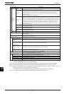
* In the event one of the error codes QER to QER and QEC to QEC appears, in which case a main
circuit component has most probably failed, the only way to reset the inverter is to turn power off and back on.
(Continued overleaf)