


E6581301
J-8
10
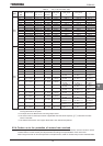
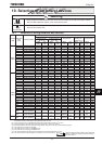
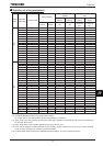
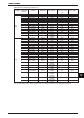
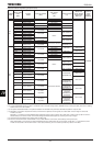
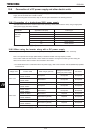
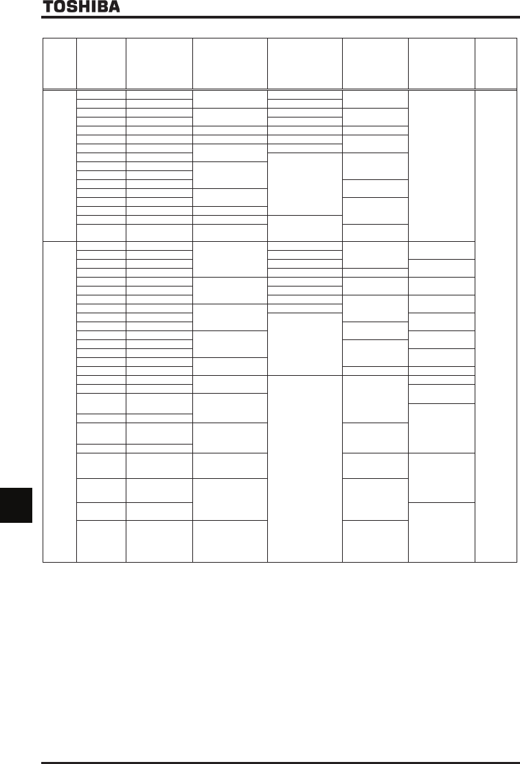
Selection table of separate-type options (2/2)
Voltage
class
Appli-cable
motor
[kW]
Inverter
model
Input AC reactor
(ACL)
DC reactor
(DCL)
(*6)
Braking resistor
(*1)
Motor end
surge voltage
suppression
filter (*4)
Control
power
supply
backup
200V
class
0.4 VFAS1-2004PL
PFL-2005S
DCL3-4015 (*5)
PBR-2007
–
CPS002Z
0.75 VFAS1-2007PL DCL3-2007
1.5 VFAS1-2015PL
PFL-2011S
DCL3-2015
PBR-2002
2.2 VFAS1-2022PL DCL3-2022
3.7/4.0 VFAS1-2037PL PFL-2018S DCL3-2037 PBR-2037
5.5 VFAS1-2055PL PFL-2025S DCL3-2055
PBR7-004W015
7.5 VFAS1-2075PL
PFL-2050S
DCL3-2075
11 VFAS1-2110PM
Built-in
PBR7-008W7R515 VFAS1-2150PM
PFL-2100S 18.5 VFAS1-2185PM
22 VFAS1-2220PM
PBR7-017W3R7
30 VFAS1-2300PM
PFL-2150S
37 VFAS1-2370PM
PBR7-035W1R845 VFAS1-2450PM PFL-2200S
55 VFAS1-2550P PFL-2300S
Attached as standard
75 VFAS1-2750P PFL-2400S
DGP600W-B1
[DGP600W-C1]
400V
class
0.75 VFAS1-4007PL
PFL-4012S
DCL3-4007
PBR-2007
MSF-4015Z
1.5 VFAS1-4015PL DCL3-4015
2.2 VFAS1-4022PL DCL3-4022
MSF-4037Z
3.7/4.0 VFAS1-4037PL DCL3-4037 PBR-4037
5.5 VFAS1-4055PL
PFL-4025S
DCL3-4055
PBR7-004W060 MSF-4075Z
7.5 VFAS1-4075PL DCL3-4075
11 VFAS1-4110PL DCL3-4110
PBR7-008W30
MSF-4150Z
15 VFAS1-4150PL
PFL-4050S
DCL3-4150
18.5 VFAS1-4185PL
Built-in
MSF-4220Z
22 VFAS1-4220PL
PBR7-017W15
30 VFAS1-4300PL
PFL-4100S
MSF-4370Z
37 VFAS1-4370PL
PBR7-017W7R545 VFAS1-4450PL
MSF-4550Z
55 VFAS1-4550PL
PFL-4150S
75 VFAS1-4750PL PBR7-017W3R7 MSF-4750Z
90 VFAS1-4900PC
PFL-4300S
Attached as standard
DGP600W-B2
[DGP600W-C2]
MSL-4215T
110
VFAS1-4110KPC
MSL-4314T
132
VFAS1-4132KPC
PFL-4400S
MSL-4481T
160
VFAS1-4160KPC
200
VFAS1-4200KPC
PFL-4600S
PB7-4200K(*2)
DGP600W-B3
[DGP600W-C3]
220
VFAS1-4220KPC
280
VFAS1-4280KPC
PFL-4800S
PB7-4200K(*2)
DGP600W-B4
[DGP600W-C4]
MSL-4759T
355
VFAS1-4355KPC
PFL-4450S
×2(parallel)
PB7-4400K(*2)
DGP600W-B3
×2(parallel)
[DGP600W-C3
×2(parallel)]
400
VFAS1-4400KPC
MSL-41188T
500
VFAS1-4500KPC
PFL-4613S
×2(parallel)
PB7-4400K(*2)
DGP600W-B4
×2(parallel)
[DGP600W-C4
×2(parallel)]
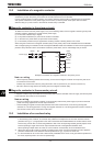
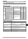
(*1): Model in square brackets is fitted with top cover.
(*2): To use a 400V/200kW inverter or larger in combination with an external braking resistor (DGP600 series), a braking unit (PB7) with a built-in braking
resistor drive circuit is also needed.
(*3): The options are selected based on the premise that 600V HIV insulated wires (continuous allowable temperature: 75°C) are used.
(*4): Each MSF-****Z model is composed of a reactor, a resistor and a capacitor, and as a guide, use a cable 300m or less in length to connect the
inverter to the motor.
Each MSL-****T model is an output-dedicated surge suppression reactor, and as a guide, use a cable 100m or less in length (or 50m or less for a
shielded cable) to connect the inverter to the motor, although allowable cable lengths vary according to the input voltage.)
(*5): These reactors are usable for each of 200V class and 400V class.
(*6): Be sure to connect DC reactor to 200V-55kW or more or 400V-90kW or more inverter. (Not necessary for DC power input.)
When a 200V-55kW or more inverter or 400V-90 to 280kW inverter is replaced with new one, the reactor (model: DCL-****) used with the current
inverter can be used as-is with the new inverter. In such cases, therefore, you do not need to purchase any reactors in this table.