


E6581301
H-6
8
8.3 Changing status monitor function
■
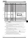
Changing the display format while power is on
The item displayed in the standard monitor mode (*1 on the left side of table on page H-2), for example, operation
frequency which is displayed by default in this way: “=” when power is on or “HH” when power is off, can be
changed to any item shown on page H-7. This new format, however, will not display an assigned prefix such as V
or E.
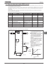
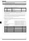
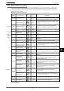
ȷStandard monitor mode
Standard monitor display selection (H)
Title Function Adjustment range Default setting
H
Standard monitor hold
function
:Real time
:Peak hold
:Minimum hold
H
Standard monitor
display selection
~
Refer to page H-7.
Specify how to output the monitored values that are assigned to status monitors 1 through 8.
If H is set to , the monitored values selected with H (standard monitor display selection parameter) are
displayed one after another.
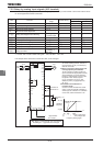
For peak hold values and minimum hold values, the minimum values in each operation mode are displayed. When
the motor is at a standstill, the values monitored last are held as they were until the motor is started the next time.
The maximum and minimum values monitored after power is turned on or after the reset with the EASY key are
always displayed no matter whether the motor is in operation or at a standstill.
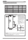
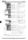
■
Changing contents of status monitor indication
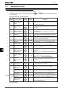
Regarding contents of status monitor indications appearing in the left column of the table on page H-2, those
marked with *2 to *9 can be changed for others. Select a desirable monitor function from among optional monitor
functions appearing on page H-7.
*2 Frequency command
Changeable by status monitor 1 display selection (H).
*3 Output current
Changeable by status monitor 2 display selection (H).
*4 Input voltage
Changeable by status monitor 3 display selection (H).
*5 Output voltage
Changeable by status monitor 4 display selection (H).
*6 Torque
Changeable by status monitor 5 display selection (H).
*7 Regenerative braking resistance overload factor
Changeable by status monitor 6 display selection (H).
*8 Inverter overload factor
Changeable by status monitor 7 display selection (H).
*9 Motor overload factor
Changeable by status monitor 8 display selection (H).
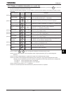
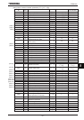
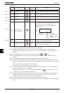
Title Function Adjustment range Default setting
H Status monitor 1 display selection ~
Refer to page H-7.
H Status monitor 2 display selection Ditto
H Status monitor 3 display selection Ditto
H Status monitor 4 display selection Ditto
H Status monitor 5 display selection Ditto
H Status monitor 6 display selection Ditto
H Status monitor 7 display selection Ditto
H Status monitor 8 display selection Ditto
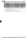
*If H to H are set at “” (Output frequency) the operation frequency is not held in trip status.