


E6581301
G-6
7
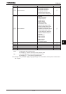
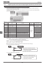
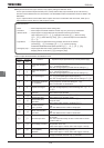
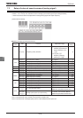
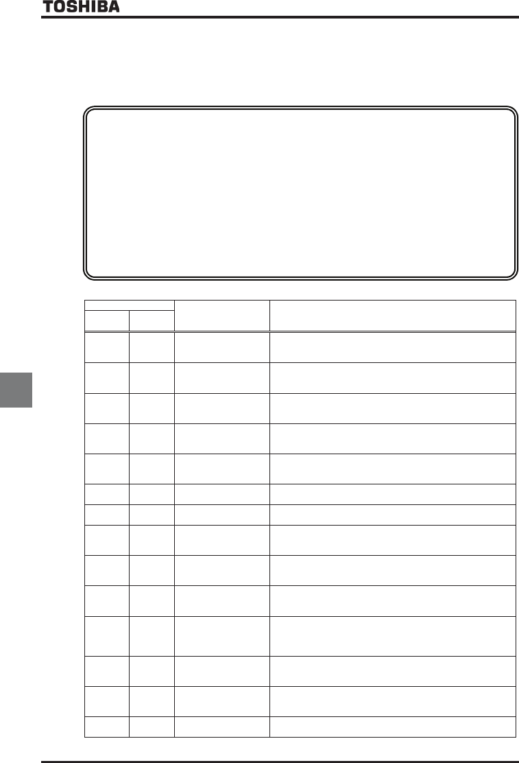
■ Output terminal function (open collector, relay outputs) setting and detection levels
For the open connector output terminals (OUT1, OUT2) and the relay output terminals (FLA, FLB and FLC),
functions can be selected from 0 to 255 functions. The selectable functions and detection levels are listed in the
table below.
Up to 7 output terminals can be used if add-on options are used in combination with the inverter, while up to 3
output terminals can be used if no add-on option is used.
Table of output terminal functions and detection levels
Parameter setting
Function Operation output specifications (in case of positive logic)
Positive
logic
Negative
logic
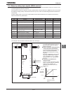
Lower limit frequency
(LL)
ON:The running frequency is equal to or higher than the setting
of NN (Lower limit frequency)
OFF:The running frequency is lower than the setting of NN.
Upper limit frequency
(UL)
ON:The running frequency is equal to or higher than the setting
of WN (Upper limit frequency)
OFF:The running frequency is lower than the setting of WN.
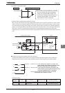
Low-speed signal
ON:The running frequency is equal to or higher than the setting
of H (low-speed signal output frequency)
OFF:The running frequency is lower than the setting of H.
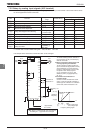
Acceleration/decelerati
on completion
ON:The difference between the frequency command and the
running frequency is within the setting of H.
OFF:In acceleration or deceleration.
Speed reach signal
ON:The running frequency is in the range of H ± H.
OFF:The running frequency is out of the range of H ±
H.
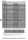
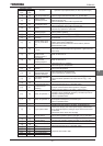
Failure FL
(All trips)
ON:Inverter is tripped.
OFF:Inverter trip is canceled.
Failure FL
(Except EF, OCL)
ON:Inverter is tripped (except GH and QEN)
OFF:Inverter trip is canceled. (reset)
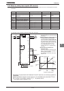
Overcurrent (OC)
pre-alarm
ON:Inverter output current is over the H (Stall prevention
level) set value.
OFF:Inverter output current is under the H.
Inverter overload
(OL1)
pre-alarm
ON:A certain rate of inverter overload (QN) detection time is
over.
OFF:The detection time is within a certain limit.
Motor overload
(OL2)
pre-alarm
ON:A certain rate of inverter overload (QN) detection time is
over.
OFF:The detection time is within a certain limit.
Overheat pre-alarm
ON:The temperature of the cooling fin is 95°C or hi gher inside
the inverter.
OFF:The temperature drops to 90°C or lower after overheat
pre-alarm was on.
Overvoltage pre-alarm
Overvoltage control operation or PB operation in progress. ON:
PB operation level + 3%
(200V class: Approx. 370Vdc, 400V class :Approx. 740Vdc)
Undervoltage in main
circuit (MOFF)
detection
ON:The main circuit voltage is lower than the main circuit
undervoltage detection (H) level.
(200V class: Approx. 170Vdc, 400V class: Approx. 340Vdc)
Low current detection
ON: The state that inverter output current is H set value
or larger continued more than H set value.
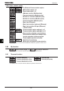
<Technical terms>
• Alarm ·······Alarm output beyond a certain setting value.
• Pre-alarm ·······Alarm output of the state where the inverter may carry out a trip by continuation.
• Serious failure ·······Output signal in a serious failure of the protection function of the inverter.
(Arm overcurrent (QEC, , ), Load side overcurrent (QEN), Short-circuiting
(GH, GH), Phase failure (GRJ, GRJ), Abnormal output current detection
(GTT))
• Light failure ·······Output signal in a slight failure of the protection function of the inverter.
(Overload (QN,), overvoltage (QR, , ), overcurrent during
acceleration/deceleration/fixed speed operation (QE, R, , R, , R))
• Emergency stop ·······Output signal when the inverter comes into emergency stop.
Stopping manner is set with H (emergency stop).