


Technobeam
®
User Manual Technobeam Laser Aiming Device™ 6-25
45. Press <Enter>, then use the <Up> and <Down> arrow keys to navigate
to the
MACR
option.
46. Press <Enter>, then use the <Up> and <Down> arrow keys to select
LRON
(laser on continuously).
47. Press <Enter> to accept your selection.
48. Look at the wall where the beam is projected onto to determine if the
laser is on.
49. If the laser does not come on, see the section titled “Troubleshooting”
on page 5-6; otherwise, continue with the next step.
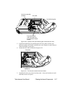
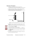
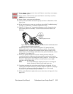
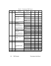
50. Figure 6-27 shows the 3 mounting/alignment screws located on the
laser aiming device assembly. See the instructions that follow the
drawing.
Figure 6-27. The laser aiming device assembly has three screws that can be
used to adjust the position of the laser.
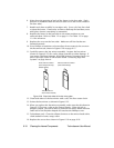
Alignment screws 1 and 3 (shown in Figure 6-27) move the laser
horizontally, and screw 2 moves the laser vertically. Use the three
alignment screws to adjust the position of the laser so that it is no
more than 2” (5 cm) directly above the center point of the beam, shown
in Figure 6-23 on page 6-19.
51. After you tighten/loosen each screw, release pressure from the
screwdriver before looking at the laser position on the wall; having
pressure on the screw can change the laser’s position.
Do not force the
screws or fully tighten them because the ends of the screws might
interfere with the dim flags.
Hint
If you have difficulty aligning the laser or turning the
screws, loosen all three screws and start over.
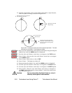
52. Continue repeating the procedure until the laser is aligned. (If you
cannot get your laser exactly at position shown in Figure 6-23 on page
6-19, but it is still at a position you think will give you enough
accuracy for your needs, you are finished.)
53. When you’re finished, replace the access door shown in Figure 6-19 on
page 6-16.
1
2
3
Mounting/alignment screws