


Technobeam
®
User Manual Setting the Beam Angle 1-13
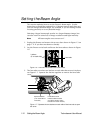
Hint
If the latches are difficult to access, reach under the lens
tube and manually turn the focus drive screw to move
the lens tube toward the rotating effects wheel.
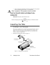
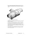
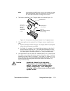
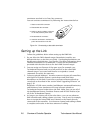
4. The factory-installed 11 to 17 degree lens set is shown Figure 1-8:
Figure 1-8. Components of the factory-installed 11 to 17 degree lens set.
5.
This step applies to the optional 8 to 12 degree narrow angle lens set
only.
a. Remove all lenses shown in Figure 1-8 and put them in a safe place
where they will not get scratched.
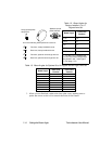
b. Use Table 1-3 on page 1-14 to install the two lenses in the 8 to 12
degree narrow angle lens set. The name and orientation of each
lens is printed on the side of the lens. The arrow printed on each
lens must point
toward the aperture
(i.e., away from the lamp).
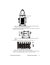
6. Lens positions in the lens tube are numbered from 1 to 10, both on the
lens tube cover and on the bottom portion of the lens tube. Use those
numbers in either Table 1-2 on page 1-14 or Table 1-3 on page 1-14 to
move the lenses to correspond with the desired beam angle. The arrow
printed on the lens must point toward the front of the fixture (i.e.,
away from the lamp).
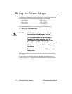
Caution Handle the lenses by the edge only.
Fingerprints can result in lower image
quality. Use only a soft, lint-free cotton
cloth to clean lenses. Use a mild glass
cleaning solution if necessary to clean built-
up dust or dirt.
Lens tube cover
Front lens
Move this lens to chang
e
the beam angle
Rear lenses
(for 11 to 17
degree lens
set only)
Always leave
these lenses
in slot 1
Arrow points to
front of fixture