


Technobeam
®
User Manual Linking the Fixtures to the Controller 2-7
Linking the Fixtures to the
Controller
Starting with the controller, link fixtures using the procedure below.
1. Consult the documentation provided with the controller for the
procedure to connect XLR cable to its Data Out connector.
2. Connect the female end of the XLR cable from the controller to the first
fixture’s male Data In connector.
3. Connect the male end of another XLR cable to the first fixture’s female
Data Out connector.
4. Continue connecting the Data Out connector from one fixture to the
Data In connector to the next fixture until you have linked all of the
Technobeam fixtures.
5. Connect other devices to the Technobeam fixtures as desired, using
the instructions in the documentation provided with those devices.
Place a male 120 ohm terminator on the female Data Out connector of
the last device in the link. The procedure for making a terminator can
be found in the section titled “Terminators” on page 2-5.
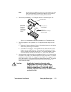
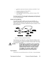
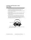
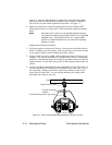
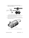
Figure 2-5. Location of the DMX data in (male) and DMX data Out (female)
ports on the fixture’s rear panel.
DMX data in (male)
DMX data out (female)
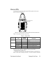
MODEL
SERIAL
FACTORY SET
DATE
Patents issued and pending. See user manual
for listings.
QC
TECHNOBEAM
29FA000 000
230V, 50Hz
1/28/98 TC