


Technobeam
®
User Manual Overview of Controller Operation 2-5
• maximum capacitance between conductor and shield - 55 pF/
ft.
• maximum resistance of 20
Ω
/1000 ft.
• nominal impedance 100–140
Ω
• 22–24 AWG with insulation having a dielectric rating of 300
volts or higher
For example, Belden
®
9841 data-grade cabling meets specifications for
EIA RS-485 applications and is highly recommended (or its equivalent)
for use with Technobeam.
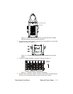
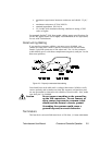
Constructing Cabling
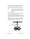
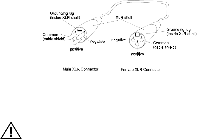
If you need to construct cabling, you must use a shielded, two-
conductor cable with a male 3-pin XLR connector on one end and a
female 3-pin XLR connector on the other end. Pin 1 is the common
(cable shield), pin 2 is the data complement (negative), and pin 3 is the
data true (positive).
Figure 2-3. Properly-constructed data cabling.
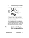
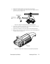
You should test each cable with a voltage/ohm meter (VOM) to verify
correct polarity and to make sure that the negative and positive pins
are not grounded or shorted to the shield or to each other. Also, make
sure that pin 1 is shielded.
Caution Do not connect anything to the ground lug
on the XLR connectors. Do not connect or
allow contact between the common (cable
shield) and the fixture’s chassis ground.
Grounding the common could cause a
ground loop and/or erratic behavior.
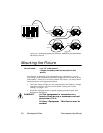
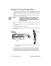
Terminators
The last device on each link must have a 120 ohm, 1/4 watt (minimum)