


ProSecure Unified Threat Management UTM10 or UTM25 Reference Manual
Virtual Private Networking Using IPsec Connections 7-47
v1.0, September 2009
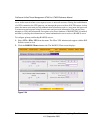
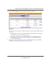
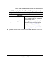
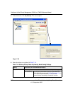
8. On the Add IKE Policy screen, complete the fields, select the radio buttons, and make your
selections from the pull-down menus as explained Table 7-16.
Note: The settings that are explained in Table 7-16 are specifically for a Mode
Config configuration. Table 7-10 on page 7-26 explains the general IKE
policy settings.
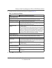
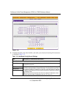
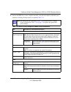
Table 7-16. Add IKE Policy Settings for a Mode Config Configuration
Item Description (or Subfield and Description)
Mode Config Record
Do you want to use
Mode Config Record?
Select the Yes radio button.
Note: Because Mode Config functions only in Aggressive Mode, selecting the
Yes radio button sets the tunnel exchange mode to Aggressive mode and
disables the Main mode. Mode Config also requires that both the local and
remote ends are defined by their FQDNs.
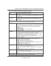
Select Mode
Config Record
From the pull-down menu, select the Mode Config record
that you created in step 5 above. In this example, we are
using NA Sales.
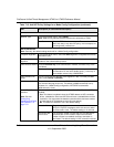
General
Policy Name A descriptive name of the IKE policy for identification and management
purposes.
Note: The name is not supplied to the remote VPN endpoint.
Direction / Type Responder is automatically selected when you select the Mode Config record
(see above). This ensures that the UTM responds to an IKE request from the
remote endpoint but does not initiate one.
Exchange Mode Aggressive Mode is automatically selected when you select the Mode Config
record (see above).
Local
Select Local Gateway
(UTM25 only)
For the UTM25 only, select a radio button to specify the WAN1 or WAN2
interface.
Identifier Type From the pull-down menu, select FQDN.
Note: Mode Config requires that the UTM (that is, the local end) is defined by a
FQDN.
Identifier Enter a FQDN for the UTM. In this example, we are using
utm25_local.com.