


ProSecure Unified Threat Management UTM10 or UTM25 Reference Manual
1-10 Introduction
v1.0, September 2009
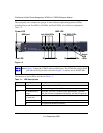
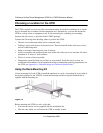
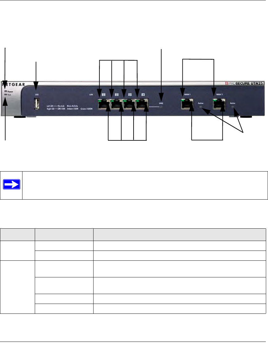
The front panel also contains three groups of status indicator light-emitting diodes (LEDs),
including Power and Test LEDs, LAN LEDs, and WAN LEDs, all of which are explained in
Table 1-1.
The function of each LED is described in Table 1-1.
Figure 1-2
Note: Figure 1-2 shows the UTM25 with two WAN ports. The UTM10 has a single WAN
port (the left WAN port that is shown in Figure 1-2) and no Active WAN LEDs.
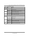
Table 1-1. LED Descriptions
Object Activity Description
Power On (Green) Power is supplied to the UTM.
Off Power is not supplied to the UTM.
Test On (Amber) during
startup.
Test mode: The UTM is initializing. After approximately 2 minutes,
when the UTM has completed its initialization, the Test LED goes off.
On (Amber) during
any other time
The initialization has failed or a hardware failure has occurred.
Blinking (Amber) Writing to flash memory (during upgrading or resetting to defaults).
Off The system has booted successfully.
Power LED
Test LED
Left LAN LEDs
Right LAN LEDs
DMZ LED
Left WAN LEDs
Right WAN LEDs
Active
WAN
LEDs
USB port