


X-STREAM
4-31
Instruction Manual
HASAxE-IM-HS
07/2006
Emerson Process Management GmbH & Co. OHG
4 Installation
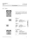
4-5-2 Wiring Inductive Loads
Switching inductive loads is a standard
application generating electromagnetic
disturbances:
The moment an inductive load (e.g. relay, valve,
etc.) is switched off, it‘s magnetic field defies
the change of current flow, generating high
voltages (up to hundrets of volts) at the coil‘s
contacts. This impulse reproduces on
connected wires and may influence electrical
equipment nearby or destroy signal inputs and/
or outputs on electronic boards.
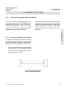
A simple measure helps to avoid such effects:
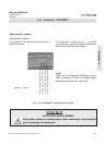
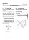
• Shunt a silicon diode to the inductive load‘s
contacts shorting the voltage impulse just
at it‘s source.
The diode‘s cathode needs to be
connected to the positive side of the coil,
the anode to the negative side (fig. 4-28).
Suitable filter components are available on
request for standard valves.
Fig. 4-28: Suppressor Diode
for Inductive Loads
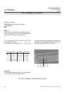
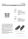
Another popular application is driving multiple
loads within one system by multiple outputs,
whereat the supply voltage for the loads is taken
from one common source.
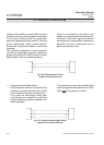
To minimize load switching generated
disturbances special care is required when
wiring the system:
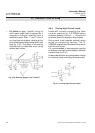
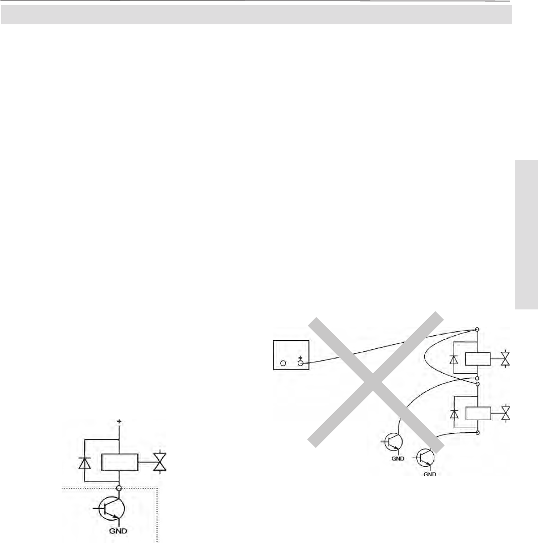
• AVOID to "serial" wire the loads‘ power
supplies with the power supply line starting
at the source and successively connecting
all loads (fig. 4-29):
4-5-3 Driving Multiple Loads
Fig. 4-29: ”Serial” Wiring
4-5 Installation - Hints on Wiring