


X-STREAM
4-14
Instruction Manual
HASAxE-IM-HS
07/2006
Emerson Process Management GmbH & Co. OHG
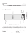
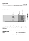
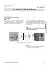
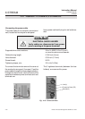
All signal cables are to be connected via screw
terminals, located at the analyzer's rear panel.
The strain reliefs provide a metal strip to connect
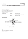
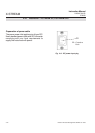
Preparation of signal cables
Supported wire cross sections: 24 to 14 AWG (0.2 to 2.5 mm
2
),
no need to use wire end sleeves
Cable skinning length: 0.354 inch (9 mm)
Hole diameter: 0.05 inch (1.2 mm)
Screw thread: M 2.5
Tightening torque, min: 3.5 in.lb (0.4 Nm)
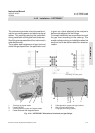
Signal inputs / outputs
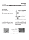
Analog signal outputs
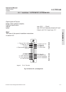
To connect the terminals remove the cover at
the analyzer's rear panel (4 screws). Feed the
analog signals cable through the uppermost
edge protection, and through the upper strain-
relief.
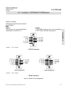
The upper 4 terminals (# 1 - 4) of the terminals
row next to the power terminals are reserved
for analog signal outputs.
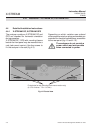
4-4-1 Installation - X-STREAM GP, X-STREAM GPS
to the cable shield after the cable's outer
insulation is stripped.
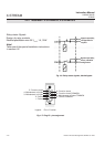
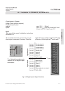
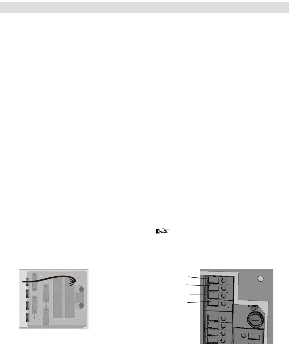
Fig. 4-11: Analog Signal Output Terminals
(+) 4 (0) - 20 mA, channel 1
(-) 4 (0) - 20 mA, channel 1
(+) 4 (0) - 20 mA, channel 2
(-) 4 (0) - 20 mA, channel 2
Note!
Take care of the special installation
instructions in section 4-5!
Interface specification:
5-4-3-4-1 Analog output setup, page 5-31
Burden: R
B
≤ 500 Ω