


X-STREAM
4-13
Instruction Manual
HASAxE-IM-HS
07/2006
Emerson Process Management GmbH & Co. OHG
4 Installation
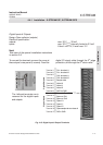
4-4-1 Installation - X-STREAM GP, X-STREAM GPS
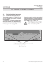
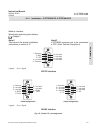
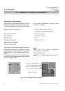
The number and assignment of gas inlet and outlet fittings depends on the application and is given
on a label attached to the analyzer's rear panel adjacent to the fittings.
For simple installation we recommend to mark the gas lines according to fig. 4-3 (In1, Out1, In2,
Out2, ...). This avoids confusion during re-installation when the analyzer had to be disconnected for
whatever reason.
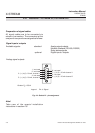
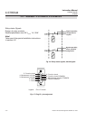
A label fixed to the inner side of the terminals cover shows how the terminals are assigned.
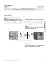
Gas inlets and outlets
Quantity: max. 8 (+ 1 optional purge gas fitting)
Specification: 6/4 mm PVDF
optional 6/4 mm or 1/4", stainles steel,
other on request
Digital inputs / outputs
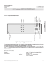
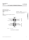
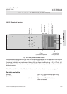
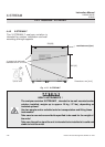
4-4-1-2 Terminals Version
Fig. 4-10: Rear panel - terminals version
Cover
(illustrated transparent)
Gas inlets
Gas outlets
Power
terminals
Power fuse
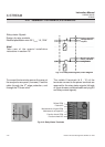
1
2
3
4
}
Strain-reliefs
Edge protection
Power fuse
4 screws for
fixing the cover
Analog outputs / relays /
Modbus interface