X-STREAM
4-21
Instruction Manual
HASAxE-IM-HS
07/2006
Emerson Process Management GmbH & Co. OHG
4 Installation
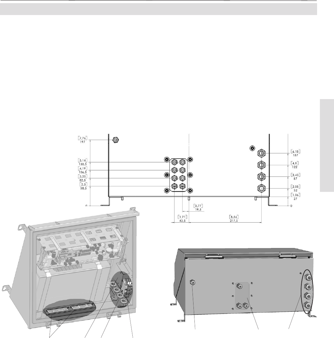
4-4-2 Installation - X-STREAM F
The instrument provides internal screw termi-
nals for connecting power and electrical signal
cables. This requires opening the instrument
during installation utilizing the sash fasteners.
Gas fittings are accessible at the instrument‘s
outer bottom side.
The number and assignment of gas inlet and
outlet fittings depends on the application and
is given on a label attached to the analyzer's
bottom side adjacent to the fittings.
For simple installation we recommend to mark
the gas lines according to the marking. This
avoids confusion during re-installation when the
analyzer had to be disconnected for whatever
reason.
Fig. 4-18: X-STREAM F -Allocation of terminals and gas fittings
5 Cable glands for power and signal cables
6 Gas inlet and outlet fittings
7 Purge gas inlet fitting (option)
1 Terminals for signal cables
2 Power EMI filter
3 4 cable glands for power and signal cables
4 Power terminals with integrated fuses
6
5
7
1423
Gas inlets
Gas outlets
1
4
Gas fittings and cable glands


