


X-STREAM
4-16
Instruction Manual
HASAxE-IM-HS
07/2006
Emerson Process Management GmbH & Co. OHG
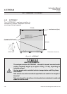
4-4-1 Installation - X-STREAM GP, X-STREAM GPS
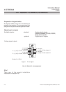
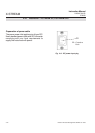
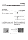
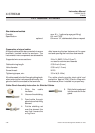
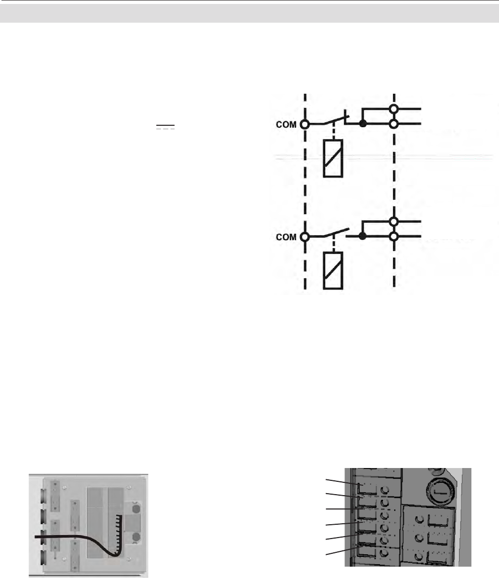
Relay status Signals
Design: dry relay contacts
Electrical specification: max. 30 V , 1 A, 30 W
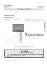
Fig. 4-13: Relay status signals, block diagram
Signal output (NC);
configuration on
request
Signal output (NO);
factory standard
configuration
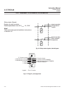
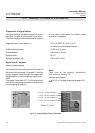
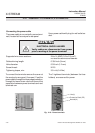
Note!
Take care of the special installation
instructions in section 4-5!
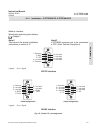
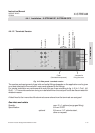
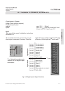
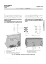
Fig. 4-14: Relay Status Terminals
To connect the terminals remove the cover at
the analyzer's rear panel (4 screws). Feed the
cable through the 3
rd
edge protection, and
through the 3
rd
strain-relief.
The middle 6 terminals (# 5 - 10) of the
terminals row next to the power terminals are
reserved for the relay status signals (left side
of figure shows a combined cable carrying RS
and relay contact signals).
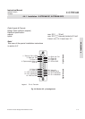
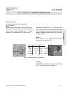
Failure COM
Failure NO
Maintenance, off-spec COM
Maintenance, off-spec NO
Function check COM
Function check NO