X-STREAM
Emerson Process Management GmbH & Co. OHG7-40
Instruction Manual
HASAxE-IM-HS
05/2006
7-4 Replacing the Electrochemical Sensor
7-4-3 Locating the Sensor
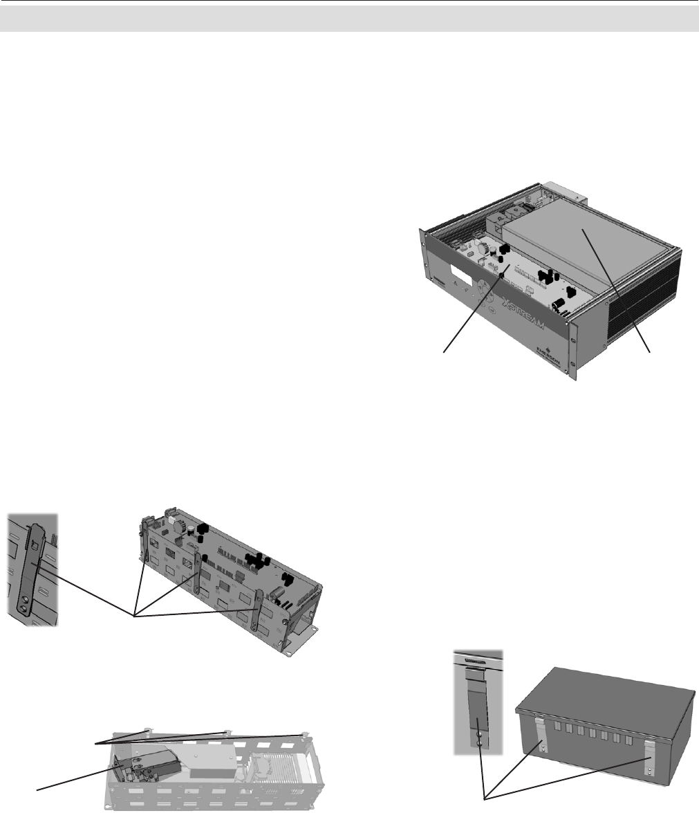
There are two options for the sensor to be
placed (fig. 7-5):
• for instruments with internal thermostatic
control the sensor unit is placed within the
electronics card cage beneath the main
board BKS.
• for instruments without internal thermos-
tatic control the sensor unit is placed inside
the physical components box.
Fig. 7-7: Allocation of eO
2
Sensor Unit
(BKS removed)
eO2
sensor unit
Detent springs
In case the sensor unit is installed inside the
physical components box, remove the box
cover to get access to the internal components:
If the cover is made of yellow plastics (used in
non-purge instruments) just lift off the cover. If
the instrument is purged, the metal cover is
secured with 2 detent springs (fig. 7-8):Press
the springs to release the cover.
Fig. 7-8: Purged Box Detail
Detent springs
Press here
to open
Detent springs
Fig. 7-6: Cardcage Detail
Push here to release
The main board is fixed in the cardcage by
means of 3 detent springs (fig. 7-6): Pushing
the upper end from the cardcage loosens the
main board allowing to take it out.
The eO
2
sensor unit is now accessible (fig. 7-7).
Fig. 7-5: X-STREAM GP Interior View
Physical
components box
Cardcage with
main board BKS
Note!
Cardcage and components box are shown on the
basis of a X-STREAM GP instrument, but look alike
in all other variations.


