


X-STREAM
4-8
Instruction Manual
HASAxE-IM-HS
07/2006
Emerson Process Management GmbH & Co. OHG
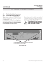
4-4-1 Installation - X-STREAM GP, X-STREAM GPS
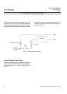
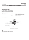
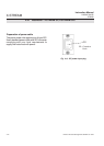
Preparation of signal cables
All signal cables are to be connected via
submin-d connectors. The connectors at the
analyzer's rear panel are assigned as follows:
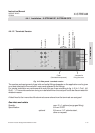
Signal inputs / outputs
Available signals: standard: Analog signal outputs
Modbus interface (RS 485; RS232)
Relay status signals
optional: Digital inputs / outputs
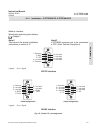
Analog signal outputs
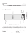
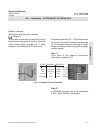
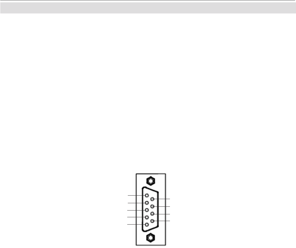
Fig. 4-4: Socket X1 - pin assignment
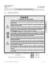
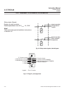
Note!
Take care of the special installation
instructions in section 4-5!
Legend: Pin # / Signal
3 / (+) 4 (0) - 20 mA, channel 1
4 / not used
5 / (+) 4 (0) - 20 mA, channel 2
6 / not used
7 / (-) 4 (0) - 20 mA channel 1
8 / not used
9 / (-) 4 (0) - 20 mA channel 2
2 / not used
1 / not used
Burden: R
B
≤ 500 Ω