


T-10
X-STREAM
Instruction Manual
HASAxE-IM-HS
05/2006
Emerson Process Management GmbH & Co. OHG
Index of Tables
Index of Tables
Table 1-1: Digital Inputs IN4-IN7, array ................................................................................................................1-20
Table 3-1: Solvent Resistant Sensor: Approved Solvents....................................................................................3-9
Table 3-2: Medium affected Materials within Paramagnetic Oxygen Sensor ...................................................3-10
Table 3-3: Paramagnetic Oxygen Measurement, cross interference by accompanying gases ........................3-13
Table 3-4: Electrochemical Oxygen Measurement, cross interference by accompanying gases ...................3-13
Table 3-5: Examples of Specific Thermal Conductivities ..................................................................................3-14
Table 3-6: Gas Components and Measuring Ranges, examples .......................................................................3-16
Table 3-7: Measurement Performance Specifications ........................................................................................3-17
Table 5-1: Analog Output Signal Selection ........................................................................................................5-35
Table 5-2: Analog Output Signal Setting & Operation Modes .......................................................................... 5-37
Table 6-1: Analog Output Signals Settings & Operation Modes .......................................................................6-10
Table 6-2: Thresholds influenced by SpanRange parameter............................................................................. 6-13
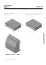
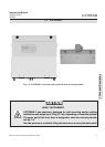
Fig. 8-0: X-STREAM F interior view with flapped front panel .............................................................................8-8
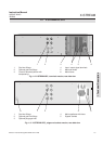
Fig. 8-1: X-STREAM interior views......................................................................................................................8-12
Fig. 8-2: BKS Board (section), measuring points ...............................................................................................8-13
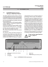
Fig. 8-3:Light barrier signal .................................................................................................................................8-15
Fig. 8-4: OXS board, assembled, top view..........................................................................................................8-17
Fig. 8-5: BKS board (section) ...............................................................................................................................8-18
Fig. 8-6: Allocation of fuse on BKS board ..........................................................................................................8-19