


X-STREAM
4-22
Instruction Manual
HASAxE-IM-HS
07/2006
Emerson Process Management GmbH & Co. OHG
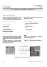
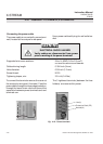
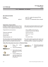
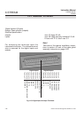
All signal cables are to be connected via screw
terminals, located inside the analyzer. The
instruments inner components are accessible
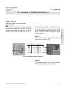
Preparation of signal cables
Supported wire cross sections: 24 to 14 AWG (0.2 to 2.5 mm
2
),
no need to use wire end sleeves
Cable skinning length: 0.354 inch (9 mm)
Hole diameter: 0.05 inch (1.2 mm)
Screw thread: M 2.5
Tightening torque, min: 3.5 in.lb (0.4 Nm)
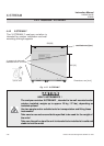
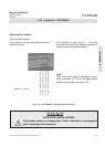
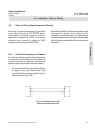
4-4-2 Installation - X-STREAM F
All cables need to be fed through cable glands
when entering the instrument and fixed by the
gland nut when connected to the terminals.
The cable glands provide strain-relief and
protection against EMI (Electro Magnetic
Interference) when installed in a proper way:
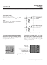
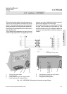
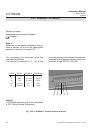
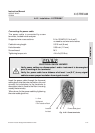
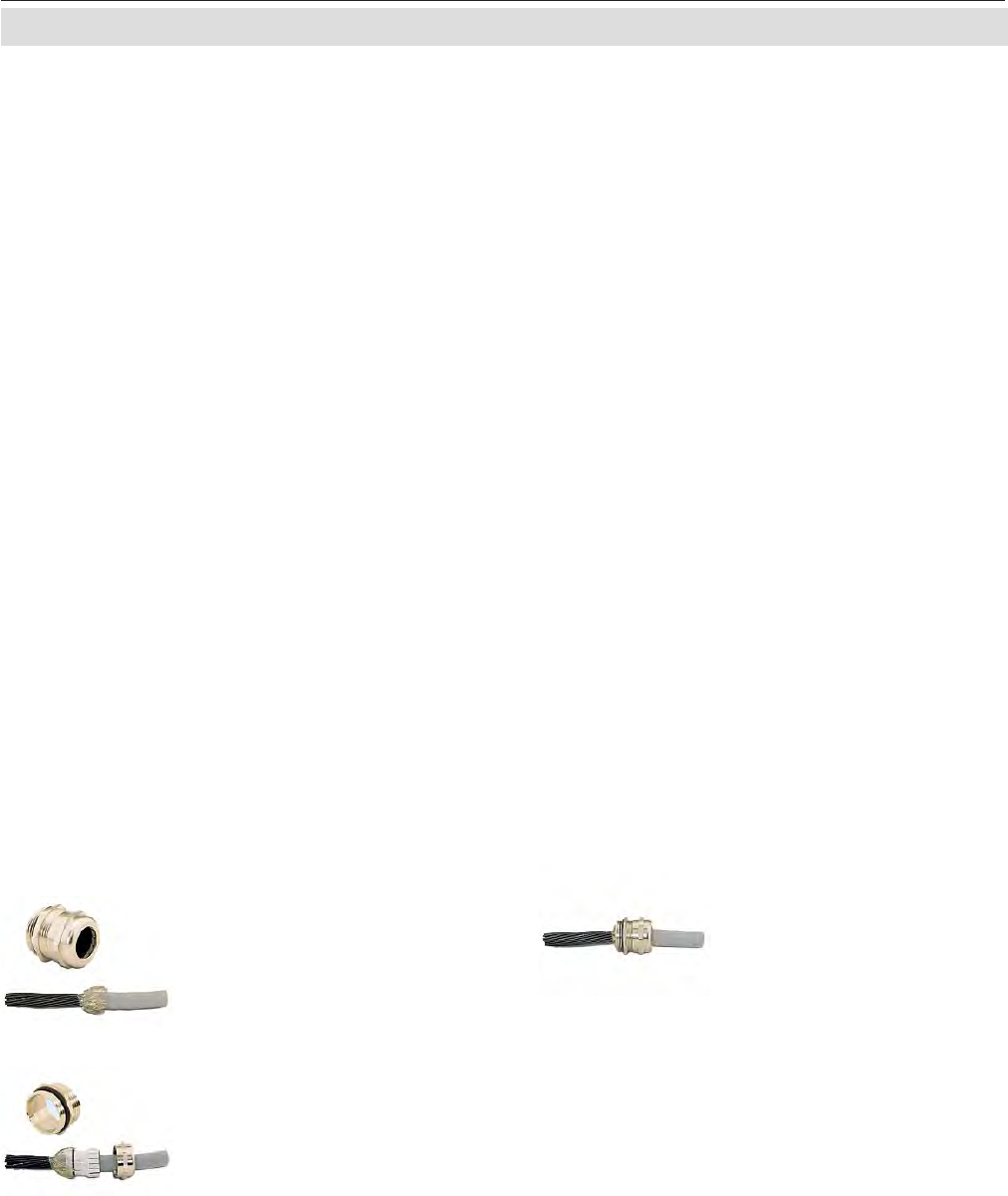
Cable Gland Assembly Instruction for Shielded Cables
3. Feed cable through
gland nut and into fixing
element
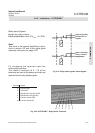
4. Put the shielding net
over the element the
way that it covers the
o-ring 2 mm.
1. Strip the cable
insulation
2. Uncover the shielding
5. Stick the fixing element
into the neck and fix the
gland.
after loosening the two fasteners at it‘s upper
end and opening the front door downwards.
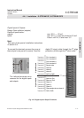
Gas inlets and outlets
Quantity: max. 8 (+ 1 optional purge gas fitting)
S
pecification: 6/4 mm PVDF
optional 6/4 mm or 1/4", stainles steel, other on request