


X-STREAM
Emerson Process Management GmbH & Co. OHG7-2
Instruction Manual
HASAxE-IM-HS
05/2006
7-2 Performing a Leak Test
To achieve best and proper measuring results
you must ensure the gas path system does not
have leaks.
The following procedure describes how to per-
form a leak test with focus on the instrument.
The gas path system should be leak tested at
least on a bimonthly basis and after
maintenance, replacement or repair of gas
path parts.
Note!
It is recommended to include external
equipment (e.g. cooler, dust filters, etc.) into
a leak test!
7-2 Performing a Leak Test
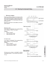
Required tools
• U-turn manometer for max. 7.25 psi
(500 mbar)
• Stop valve
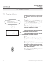
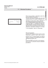
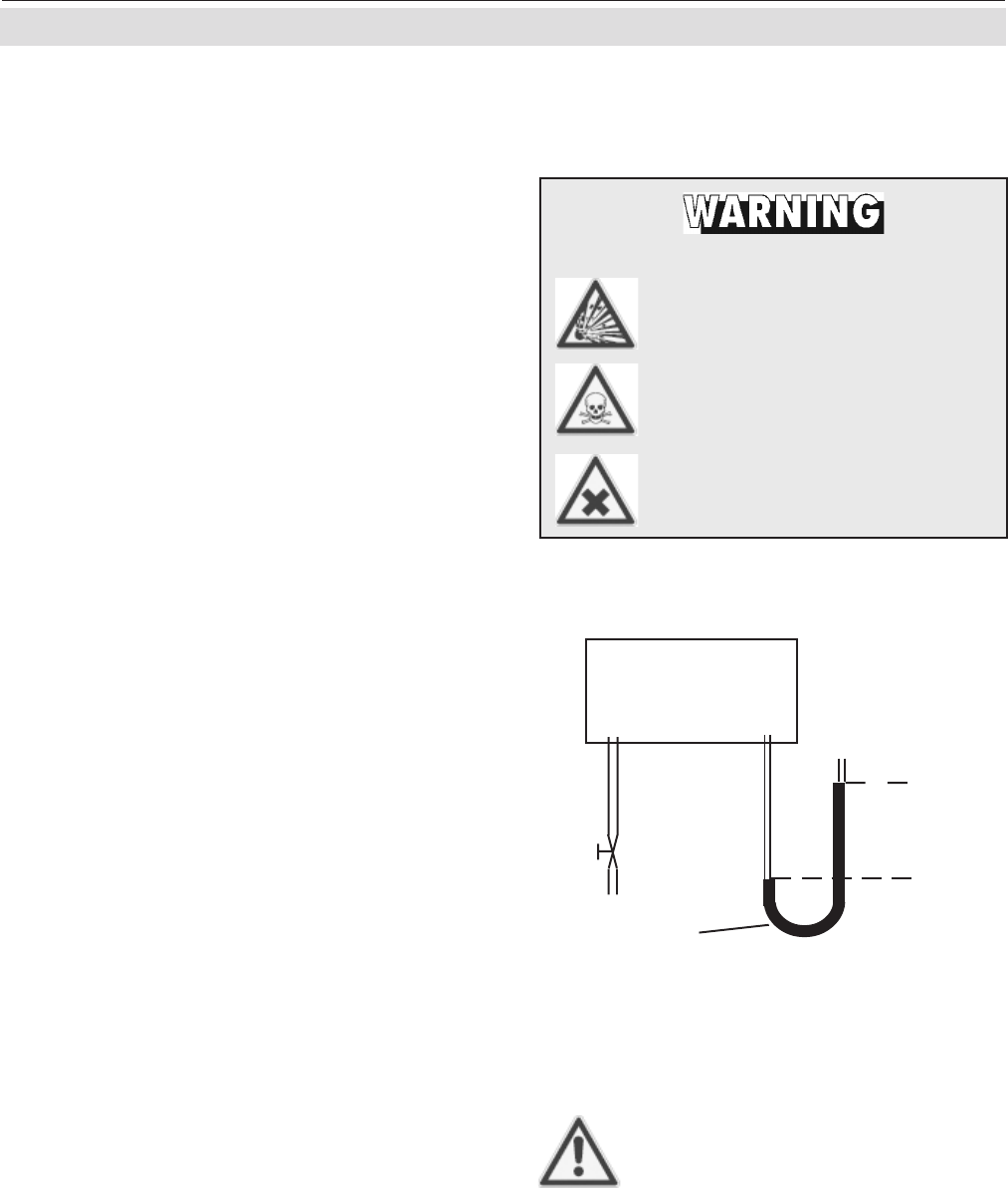
Procedure
• Connect the water filled u-turn manometer
to the analyzer‘s sample gas output
(disconnect external gas lines).
• Install the stop valve between gas input
fitting and a Nitrogen (N
2
) supply.
• Open the stop valve until the internal gas
path is under pressure of approx. 0.725
psi/50 mbar (corresponding to 19.7 inch/
500 mm water column)
• Close the stop valve. After a short time for
the water to balance the water level must
not change over a time period of approx.
5 minutes!
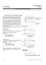
HAZARD FROM GASES !
Before opening gas paths they
must be purged with ambient
air or neutral gas (N
2
) to avoid
hazards caused by toxic, flam-
mable, explosive or harmful to
health sample gas compo-
nents!
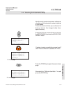
Analyzer
overpressure
approx.
0.725 psi/50 mbar
stop
valve
Water
Fig. 7-1: Leak Testing with
U-turn Manometer
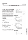
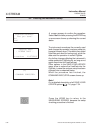
Max. pressure 7.25 psig (500 mbar)!
Dual channel instruments:
Analyzers with parallel tubing
require separate leak tests for
each gas path !