X-STREAM
Instruction Manual
HASAxE-IM-HS
05/2006
1-18 Emerson Process Management GmbH & Co. OHG
1-8 Optional Interfaces
1-8 Optional Interfaces
Optionally available are the following interfaces
(in combination only):
• 8 digital outputs
• 7 digital inputs
The interface signals are provided at submin-
d-connectors or screw terminals, depending on
analyzer model.
1-8-2 Digital Inputs
Digital inputs are required for remotely starting
calibration proceduresor activating valves or
the optional internal pump by simply supplying
a voltage.
Electrical data
LOW: U
in
< 1.5 V
HIGH: U
in
> 4.5 V
Input resistance: 57.5 kΩ
(Voltages to be measured against the reference
terminal labeled "IN GND").
Inputs protected against overvoltage up to
approx. 40 V. Open inputs are at LOW level.
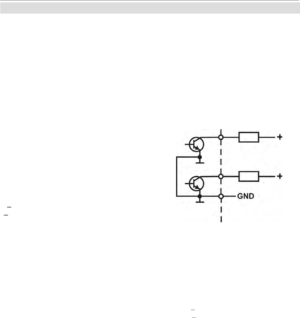
1-8-1 Digital Outputs
Digital outputs are required for reporting con-
centration alarms to external systems (e.g. data
aquisition systems) and/or for controlling
external valves (e.g. for automatic calibration).
Digital outputs are "open collector" outputs,
optically isolated against the instrument's
electronics. Outputs are not protected against
short circuits.
Electrical data
U < 30 V dc
I < 30 mA dc
Remaining voltage when activated: < 2 V
Common GND ( - ) for all outputs.
Fig. 1-13: Digital Outputs - Schematic
Out 1
Out 2
"+" and "GND" from external power supply
load
load
Inside analyzer Outside analyzer


