


SJ300 Inverter
Configuring Drive
Parameters
3–49
Intelligent Input
Terminal
Overview
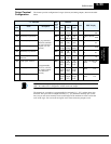
Each of the eight intelligent terminals may be assigned any of the options in the following
table. When you program one of the option codes for terminal assignments C001 to C008, the
respective terminal assumes the function role of that option code. The terminal functions have a
symbol or abbreviation, which we use to label a terminal using that function. For example the
“Reverse Run” command is [RV]. The physical label on the terminal block connector is simply
1, 2, 3, 4, 5, 6, 7, or 8. However, schematic examples in this manual also use the terminal
function symbol (such as [RV]) to show the assigned option. The option codes for C011 to
C019 determine the active state of the logical input (active high or active low).
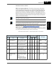
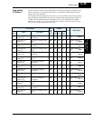
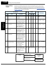
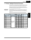
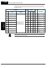
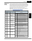
Summary Table - This table shows all forty-four intelligent input functions at a glance.
Detailed descriptions of these functions, related parameters and settings, and example wiring
diagrams are in “
Using Intelligent Input Terminals” on page 4–11.
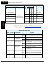
Input Function Summary Table
Option
Code
Terminal
Symbol
Function Name Description
01 RV Reverse Run/Stop ON Inverter is in Run Mode, motor runs reverse
OFF Inverter is in Stop Mode, motor stops
02 CF1 Multi-speed select,
Bit 0 (LSB)
ON Binary encoded speed select, Bit 0, logical 1
OFF Binary encoded speed select, Bit 0, logical 0
03 CF2 Multi-speed select,
Bit 1
ON Binary encoded speed select, Bit 1, logical 1
OFF Binary encoded speed select, Bit 1, logical 0
04 CF3 Multi-speed select,
Bit 2
ON Binary encoded speed select, Bit 2, logical 1
OFF Binary encoded speed select, Bit 2, logical 0
05 CF4 Multi-speed select,
Bit 3 (MSB)
ON Binary encoded speed select, Bit 3, logical 1
OFF Binary encoded speed select, Bit 3, logical 0
06 JG Jogging ON Inverter is in Run Mode, output to motor runs at jog
parameter frequency A038
OFF Inverter is in Stop Mode
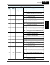
07 DB External Signal for DC
Injection Braking
ON DC braking will be applied during deceleration
OFF DC braking will not be applied
08 SET Set (select) 2nd Motor
Data
ON The inverter uses 2nd motor parameters for generat-
ing frequency output to motor
OFF The inverter uses 1st (main) motor parameters for
generating frequency output to motor
09 2CH 2-stage Acceleration
and Deceleration
ON Frequency output uses 2nd-stage acceleration and
deceleration values
OFF Frequency output uses standard acceleration and
deceleration values
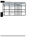
11 FRS Free-run Stop ON Causes output to turn OFF, allowing motor to free run
(coast) to stop
OFF Output operates normally, so controlled deceleration
stops motor
12 EXT External Trip ON When assigned input transitions OFF to ON, inverter
latches trip event and displays E12
OFF No trip event for ON to OFF transition; any recorded
trip events remain in history until Reset