


SJ300 Inverter
Configuring Drive
Parameters
3–59
Serial
Communications
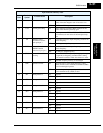
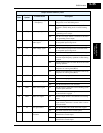
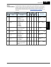
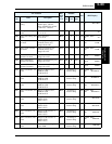
The following table configures the communications port of the SJ300 inverter. You can have up
to thirty-two devices on the serial communications network. The inverters are slaves and the
computer or digital operator is the master. Thus, all inverters on the serial connection must use
the same baud rate, data length, parity, and stop bits. However, each device on the serial
network must have a unique node address. See “
Serial Communications” on page B–1 for more
information.
“C” Function
Run
Mode
Edit
Lo Hi
Defaults
Units
SRW Display
Func.
Code
Name Description
–FE
(CE)
–FU
(UL)
–FR
(Jpn)
C070 Data command method Four option codes:
02 Digital operator
03 RS485
04 Expansion card #1
05 Expansion card #2
✘ ✘ 02 02 02 —
>C070 PARAM
SELECT REM
C071 Communication speed
selection
Five option codes:
02 (Test)
03 2400bps
04 4800bps
05 9600bps
06 19200bps
✘ ✔ 04 04 04 bps
>C071 RS485
BAU 4800bps
C072 Node allocation Set the address of the
inverter on the network.
Range is 1 to 32.
✘ ✔ 1. 1. 1. —
>C072 RS485
ADDRESS 01
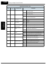
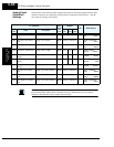
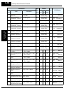
C073 Communication data
length selection
Two option codes:
07 7-bit data
08 8-bit data
✘ ✔ 777—
>C073 RS485
BIT 7BIT
C074 Communication parity
selection
Three option codes:
00 No parity
01 Even parity
02 Odd parity
✘ ✔ 00 00 00 —
>C074 RS485
PARITY NO
C075 Communication stop bit
selection
Two option codes:
01 1 stop bit
02 2 stop bits
✘ ✔ 111—
>C075 RS485
STOPBIT 1BIT
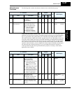
C078 Communication wait
time
Time the inverter waits after
receiving a message before it
transmits. Range is 0.0 to
1000 ms
✘ ✔ 0. 0. 0. —
>C078 RS485
WAIT 0000ms