


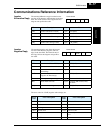
Communications Reference Information
Appendix B
B–18
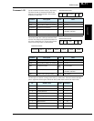
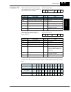
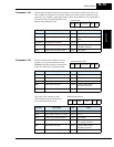
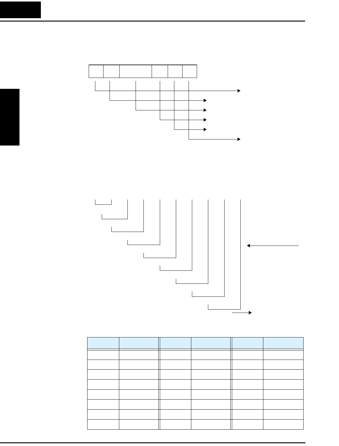
Block Check
Code (BCC)
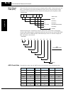
This section shows how the inverter protocol computes defines a BCC—block check code. The
BCC is calculated for each frame transmitted and can be used to verify the integrity of data
transmission. The example below shows command 01 setting the inverter frequency to 5Hz.
The block check code is computed by using the ASCII codes (shown above) and applying
eXclusive OR (XOR) operations. Beginning with the first pair of bytes, the result of their XOR
result is then used in an XOR operation with the third byte, and so on. For this example, the
BCC calculation is shown below.
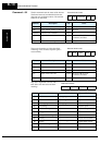
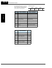
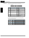
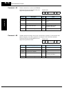
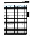
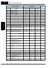
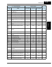
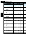
ASCII Code Table The table below shows only the ASCII codes used for function codes and parameter data.
STX Node Command Data BCC [CR]
Frame format
ASCII Code
(0x 02)
(0x 30 31)
(0x 30 31)
(0x 30 30 30 35 30 30)
(0x 30 35)
(0x 0D)
0 1
0 1
0 0 0 5 0 0
0
Data bytes:
3 0 3 03 53 03 03 03 13 03 1
0 1
3 0
3 1
0 0
3 0
0 0
3 0
0 5
3 5
0 5
BCC
XOR
intermediate results
Character ASCII Code Character ASCII Code Character ASCII Code
STX 0 2 4 3 4 C 4 3
ACK 0 6 5 3 5 D 4 4
CR 0 D 6 3 6 E 4 5
NAK 1 5 7 3 7 F 4 6
03 0838H4 8
13 1939P5 0
2 3 2 A 4 1
——
3 3 3 B 4 2
——