


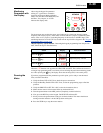
SJ300 Inverter
Inverter Mounting
and Installation
2–25
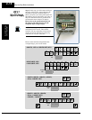
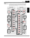
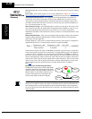
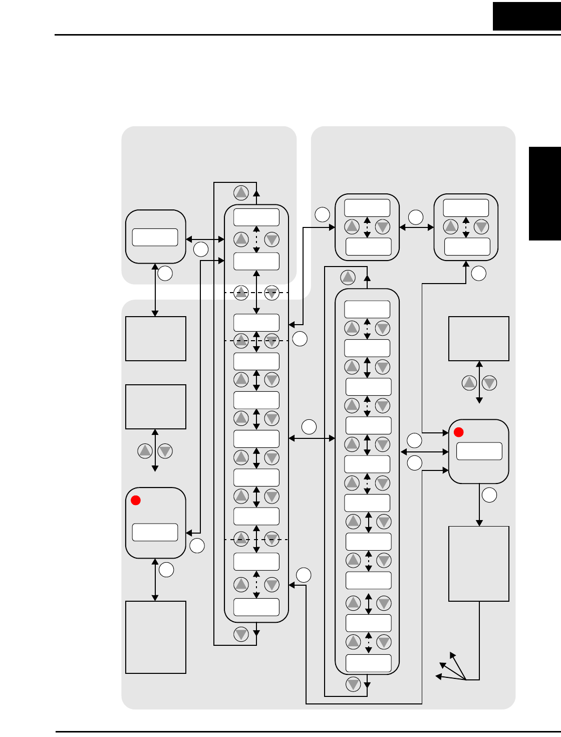
Keypad
Navigational Map
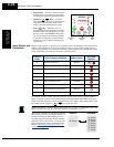
The SJ300 Series inverter drives have many programmable functions and parameters. Chapter 3
will cover these in detail, but you need to access just a few items to perform the powerup test.
The menu structure makes use of function codes and parameter codes to allow programming
and monitoring with only a 4-digit display and a few keys and LEDs. So, it is important to
become familiar with the basic navigational map of parameters and functions in the diagram
below. You can later use this map as a reference.
1
2
2
1
Write
data to
EEPROM,
store as
powerup
default
Increment/
decrement
value
2
1
2
1
2
1
2
1
2
1
2
1
2
1
1
Select ParameterSelect Function
Display Data
2
Return to
parameter
list
2
1
2
1
2
1
2
1
2
1
2
1
Edit Parameter
FUNC.
FUNC.
FUNC.
2
1
2
1
2
1
2
1
2
1
2
1
d o90
U–––
P–––
H–––
C–––
b –––
A–––
Uo1 2
Uo01
Po49
Po01
ho72
ho01
c1 23
co01
b 126
b o01
a1 32
ao01
123.4
0.00
d o01
Fo04
Fo01
FUNC.
FUNC.
FUNC.
2
1
Po49
d 001
FUNC.
STR
FUNC.
D002–D090
Edit
0.00
D001
Edit
PRG LED
PRG LED
Increment/
decrement
value
1
2
FUNC.
Write data
to F001,
store D001
as power-
up default
STR
FUNC.
STR
Store as
powerup
default
Monitor Mode Program Mode