


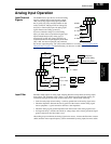
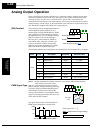
Analog Input Operation
Operations
and Monitoring
4–60
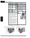
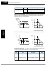
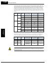
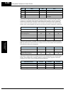
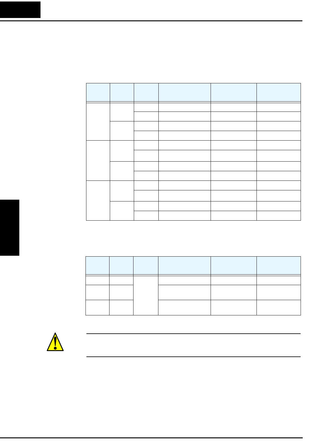
The following tables show the available analog input settings. Parameters A006, A005, and
input terminal [AT] determine the External Frequency Command input terminals that are avail-
able and how they function. The Trim Frequency input [O2]—[L] is available (when check
marked) for some settings. Other settings make the reverse direction (in addition to forward)
available for bipolar input settings (when check marked). A bipolar input responds to positive
input voltages with a forward motor rotation, and to negative input voltages with reverse motor
rotation.
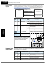
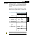
The table below applies when the [AT] input function is not assigned to any intelligent input
terminal. The A005 setting, normally used in conjunction with an [AT] input, is ignored.
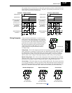
CAUTION: Whenever the [AT] input function is not assigned to any input terminal and
reverse rotation is not desired or is unsafe, be sure to set A006 = 01. This setting makes the
[O2] input unipolar only.
A006 A005 [AT]
External Frequency
Command Input
Trim Frequency
Command Input
Reverse avail.
(bipolar input)
00 00 OFF [O] ✘✘
ON [OI] ✘✘
01 OFF [O] ✘✘
ON [O2] ✘✔
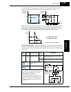
01 00
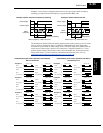
Example
1
OFF [O] [O2] ✘
ON [OI] [O2] ✘
01 OFF [O] [O2] ✘
ON [O2] ✘✔
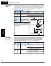
02 00
Example
2
OFF [O] [O2] ✔
ON [OI] [O2] ✔
01 OFF [O] [O2] ✔
ON [O2 ✘✔
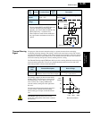
A006 A005 [AT]
External Frequency
Command Input
Trim Frequency
Command Input
Reverse avail.
(bipolar input)
00 —
(not
assigned
to any
input
terminal)
[O2] ✘✔
01 — Summation of
[O] and [OI]
[O2] ✘
02 — Summation of
[O] and [OI]
[O2] ✔