


Analog Output Operation
Operations
and Monitoring
4–62
Analog Output Operation
In the system design for inverter applications it is sometimes useful to monitor inverter opera-
tion from a remote location. In some cases, this requires only a panel-mounted analog meter
(moving-coil type). In other cases, a controller device such as a PLC may monitor and
command the inverter frequency and other functions. The inverter can transmit the (real-time)
output frequency, current, torque, or other parameters to the controller to confirm actual opera-
tion. The monitor output terminal [FM] serves these purposes.
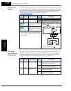
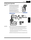
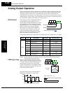
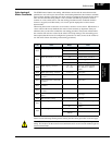
[FM] Terminal The inverter provides an analog/digital output on
terminal [FM] (frequency monitor). It uses
terminal [CM1] as digital GND reference. While
many applications use this terminal to monitor
the output frequency, you can configure terminal
[FM] to transmit one of several parameters.
Most use pulse-width modulation (PWM) to
represent the value, while one parameter uses
frequency modulation (FM) to represent the
value. Do not confuse the notation for terminal
[FM] (with brackets) with FM signal type.
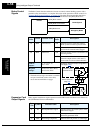
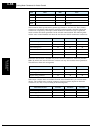
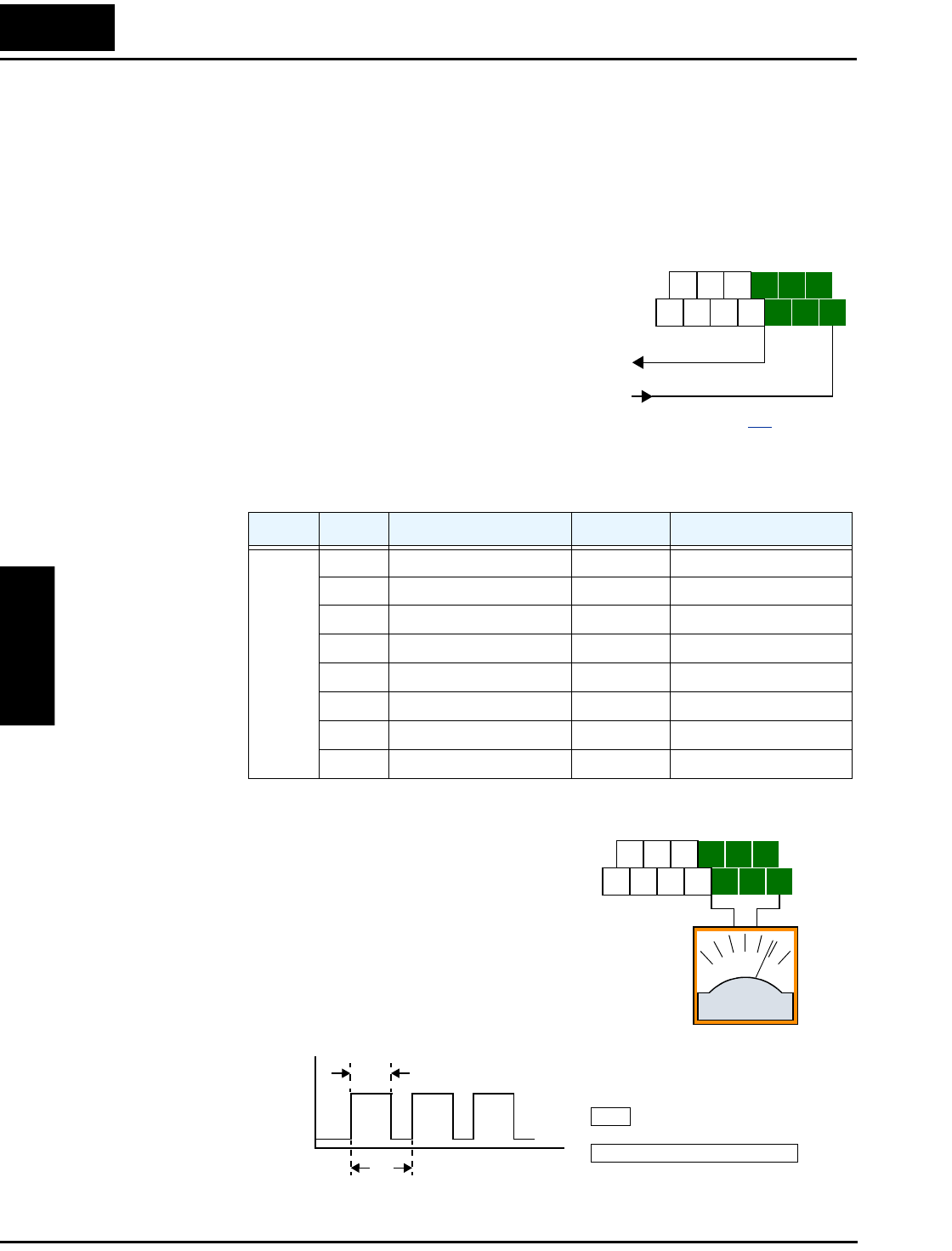
The following table lists the configurations for terminal [FM]. Use function C027 to configure.
Note 1: Display substitutes only during sensorless vector control, 0Hz domain sensorless
vector control, and vector control
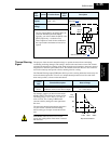
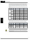
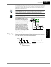
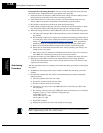
PWM Signal Type The pulse-width modulated signal at terminal
[FM] is primarily designed for driving a moving-
coil meter. The pulse-width modulated signal is
automatically averaged by the inertia of the
moving-coil mechanism—converting the PWM
signal to an analog representation. Be sure to use
a 10V full-scale DC voltmeter.
The signal characteristics of terminal [FM] in
PWM signal configuration is shown below
Func. Code Description Waveform Full Scale Value
C027
00 Output frequency PWM 0 – Max. frequency (Hz)
01 Output current PWM 0 – 200%
02 Output torque *1 PWM 0 – 200%
03 Output frequency FM 0 – Max. frequency (Hz)
04 Output voltage PWM 0 – 100%
05 Input electric power PWM 0 – 200%
06 Thermal load ratio PWM 0 – 100%
07 LAD frequency PWM 0 – Max. frequency (Hz)
D GND
Analog/digital Output
See I/O specs on page 4–9.
H O2
FM
AM
O OIL
FW
TH
PLC
P24
CM1
AMI
H O2
FM
AM
O OIL
FW
TH
PLC
P24
CM1
AMI
+–
0 to 10V,
1 mA
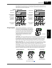
[FM]
[FM] output value
t
T
---=
Period T = 6.4ms constant (156 Hz)
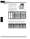
Selects FM type output
= [FM] terminal 8-bit gain setting
B081
C27=00, 01, 02, 04, 05, 06, 07
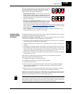
t
10V
0V
t
T