


SJ300 Inverter
Operations
and Monitoring
4–45
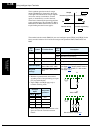
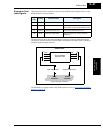
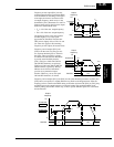
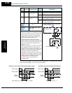
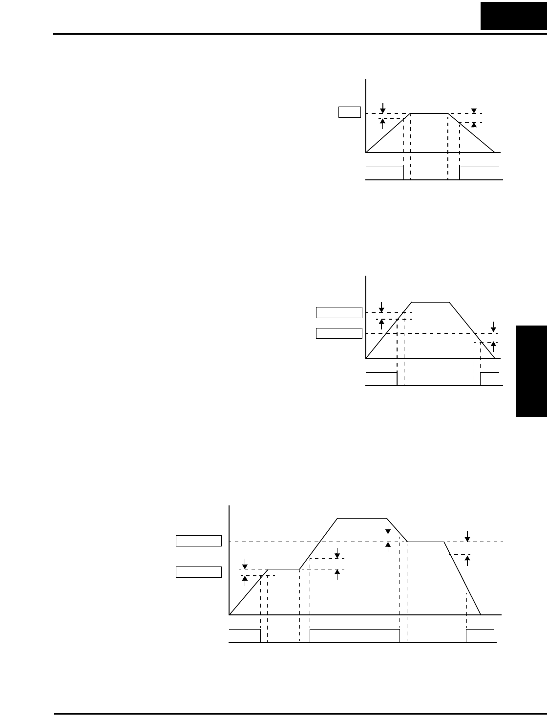
Frequency arrival output [FA1] uses the
standard output frequency (parameter F001)
as the threshold for switching. In the figure
to the right, the inverter accelerates to the
set output frequency, which serves as the
threshold for [FA1]. Parameters F
on
and F
off
illustrate the hysteresis that prevents output
chatter near the threshold value.
•F
on
is 1% of the max. output frequency
•F
off
is 2% of the max. output frequency
The hysteresis effect causes the output to
turn ON slightly early as the speed
approaches the threshold. Then the turn-
OFF point is slightly delayed. The 1% and
2% values also apply to the remaining
Frequency arrival outputs, discussed below.
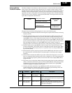
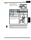
Frequency Arrival outputs [FA2] and
[FA4] work the same way; they just use
two separate threshold pairs as shown in
the figure. These provide for separate
acceleration and deceleration thresholds
to provide more flexibility than for
[FA1]. [FA2] uses C042 and C045 for
ON and OFF thresholds, respectively.
[FA4] uses C043 and C046 for ON and
OFF thresholds, respectively. Having
different accel and decel thresholds
provides an asymmetrical output
function. However, you can use equal
ON and OFF thresholds, if desired.
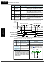
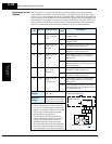
Frequency Arrival outputs [FA3] and [FA5] use the same threshold parameters as [FA2] and
[FA4] above, but operate in a slightly different way. Refer to the diagram below. After the
frequency arrives at the first threshold during acceleration and turns ON [FA3] or [FA5], they
turn OFF again as the output frequency accelerates further. The second thresholds work
similarly during deceleration. In this way, we have separate ON/OFF pulses for acceleration
and deceleration.
FA1
Output
frequency
F001
ON
t
Hz
Threshold
F
on
F
off
0
FA2/FA4
Output
frequency
C042/C045
C043/C046
ON
t
Hz
Thresholds
F
on
F
off
0
FA3/FA5
Output
frequency
C042/C045
C043/C046
ON ON
t
Hz
Thresholds
F
on
F
off
F
on
F
off
0