


Using Intelligent Input Terminals
Operations
and Monitoring
4–18
Set Second or
Third Motors
If you assign the [SET] or [SET3] functions to an intelligent input terminal, you can select
between two or three sets of motor parameters. You may assign one or both of these functions.
These second and third parameters store alternate sets of motor characteristics. When terminal
[SET] or [SET3] is turned ON, the inverter will use the second or third set of parameters
accordingly, generating the frequency output to the motor. When changing the state of the
[SET] or [SET3] input terminal, the change will not take effect until the inverter is stopped.
When you turn ON the [SET] or [SET3] input, the inverter operates per the second or third set
of parameters, respectively. When the terminal is turned OFF, the output function returns to the
original settings (first set of motor parameters). Refer to “
Configuring the Inverter for Multiple
Motors” on page 4–72 for details.
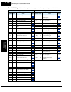
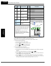
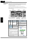
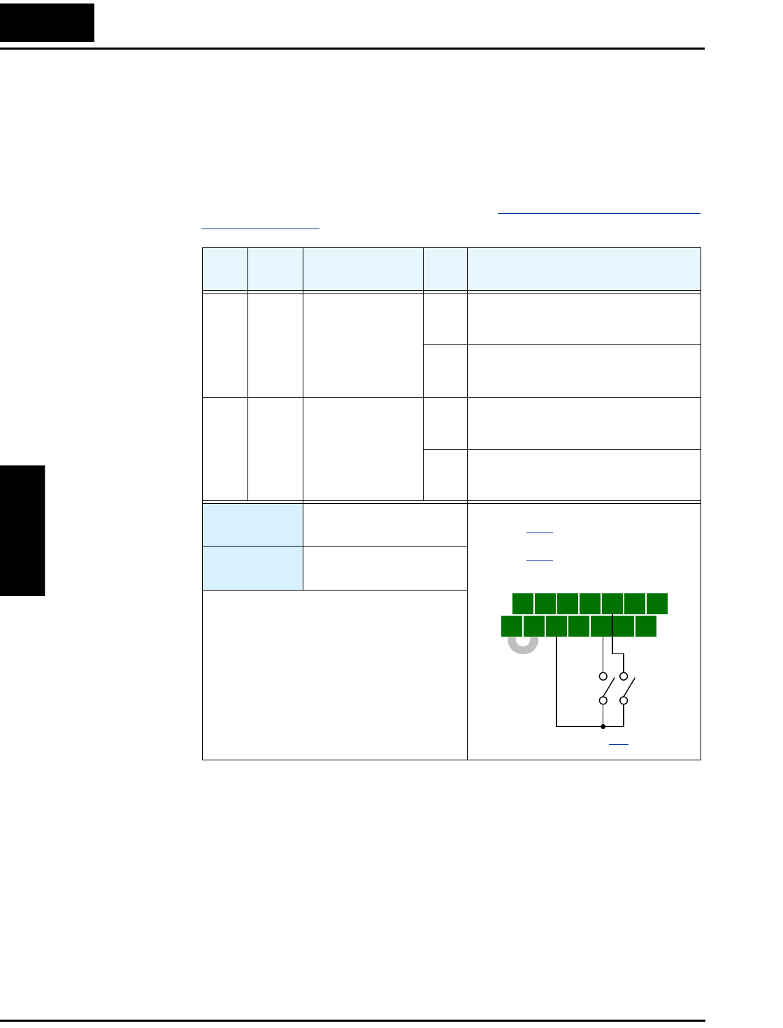
Opt.
Code
Symbol Function Name
Input
State
Description
08 SET Set 2nd Motor ON causes the inverter to use the 2nd set of
motor parameters for generating the
frequency output to motor
OFF causes the inverter to default to the 1st
(main) set of motor parameters for gener-
ating the frequency output to motor
17 SET3 Set 3rd Motor ON causes the inverter to use the 3rd set of
motor parameters for generating the
frequency output to motor
OFF causes the inverter to default to the 1st
(main) set of motor parameters for gener-
ating the frequency output to motor
Valid for
inputs:
C001, C002, C003, C004,
C005, C006, C007, C008
Required
settings:
(none)
Notes:
• If the terminal state is changed while the
inverter is running, the inverter continues
using the current set of parameters until the
inverter is stopped.
• If both SET and SET3 are ON at the same
time, SET prevails and the 2nd motor param-
eters are in effect.
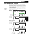
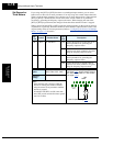
5 3 1
7 6 4 2
8
FW
TH
PLC
CM1
P24
CM1
See I/O specs on page 4–9.
Example: (Requires input configuration—
see page 3–47
. Jumper position shown is
for –xFU/-xFR models; for –xFE models,
see page 4–12
.)
SET
SET3