


Using Intelligent Output Terminals
Operations
and Monitoring
4–58
Brake Control
Signals
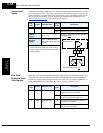
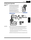
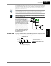
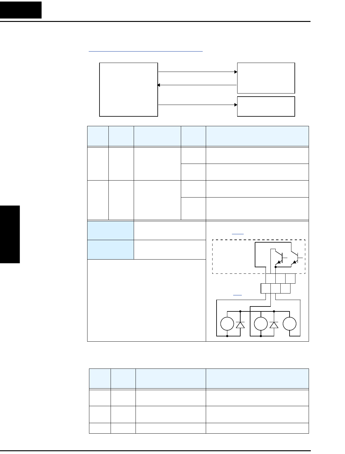
The Brake Control function enables the inverter to control external braking systems with a
particular safety characteristic. A complete discussion of the operation of brake control is in
“
External Brake Control Function” on page 4–39. The block diagram and table that follow
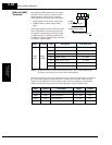
describe the configuration of the outputs [BRK] Brake Release and [BER] Brake Error.
Expansion Card
Output Signals
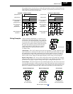
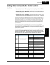
Other outputs listed below require expansion card SJ-FB Encoder Feedback board. Please see
the SJ-FB manual for more information.
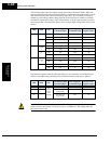
Opt.
Code
Symbol Function Name
Output
State
Description
19 BRK Brake Release ON when the inverter signals the external
brake system to release (open) its brake
OFF when the inverter is not driving the motor,
and needs the external brake engaged
20 BER Brake Error ON when the output current is less than the set
releasing current
OFF when the brake function is not in use, or
when the output current to the motor is
correct and it is safe to release the brake
Valid for
outputs:
11, 12, 13, 14, 15,
AL0 – AL2
Required
settings:
B120, B121, B122, B123,
B124, B125, B126
Notes:
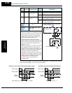
• The brake release logic convention is such that
an open circuit fault (such as loose wire)
causes the external brake to engage.
[BRK] Brake release
[BOK] Brake confirmation
Inverter
Brake System
Emergency Brake
[BER] Brake error
CM2
1314
15
11
12
See I/O specs on
page 4–9
.
Inverter output
terminal circuit
RY
+
–
RY
Example: (Requires output configuration—
see page 3–53
.)
BRK
BER
Opt.
Code
Symbol Function Name Description
21 ZS Zero Speed Detect signal Signal indicates the encoder pulses of the
motor have stopped
22 DSE Speed Deviation Excessive Velocity error exceeds the error threshold
defined by parameter P026
23 POK Positioning Completion Indicates the load position is at the target