


Using Intelligent Input Terminals
Operations
and Monitoring
4–22
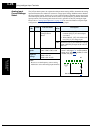
Unattended Start
Protection
If the Run command is already present when power is turned ON, the inverter starts running
immediately after powerup. The Unattended Start Protection (USP) function prevents that
automatic startup, so that the inverter will not run without outside intervention. When USP is
active, there are two ways to reset an alarm and resume running:
1. Turn the Run command OFF, or
2. Perform a reset operation by the terminal [RS] input or the keypad Stop/reset key
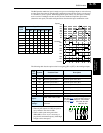
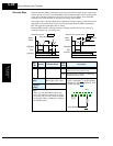
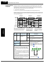
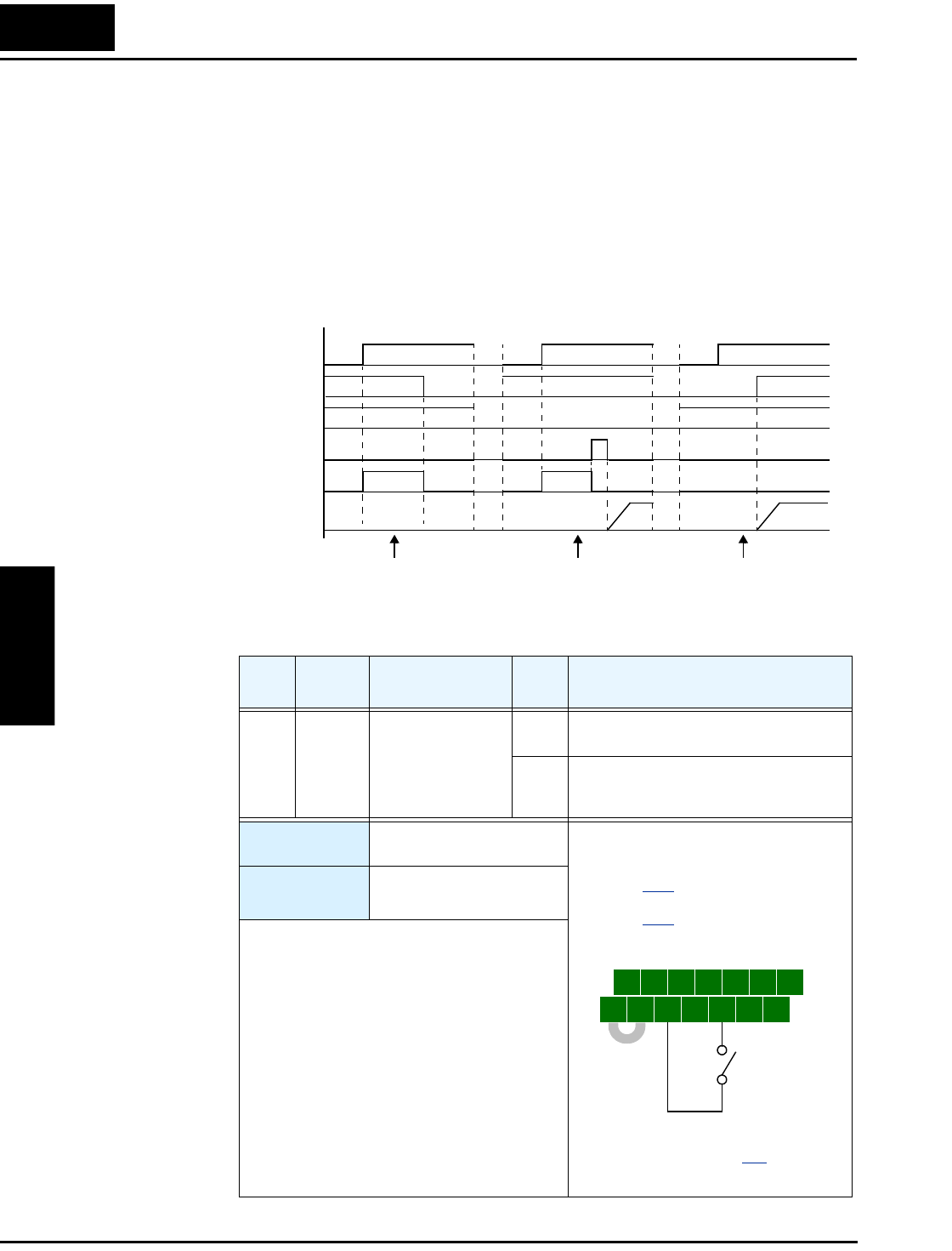
The three examples below show how the USP function works in the scenarios described at the
bottom of the diagram. The error code E13 indicates the USP trip state and corresponds to the
Alarm signal in the diagram.
Opt.
Code
Symbol Function Name
Input
State
Description
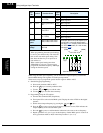
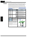
13 USP Unattended Start
Protection
ON At powerup, the inverter will not resume a
Run command
OFF At powerup, the inverter will resume a
Run command that was active before
power loss
Valid for inputs:
C001, C002, C003, C004,
C005, C006, C007, C008
Required
settings:
(none)
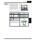
Notes:
• Note that when a USP error occurs and it is
canceled by a reset from the [RS] terminal
input or keypad, the inverter restarts immedi-
ately.
• Even when the trip state is canceled by turning
the terminal [RS] ON and OFF after an under-
voltage trip E09 occurs, the USP function will
be performed.
• When the Run command is active immediately
after the power is turned ON, a USP error will
occur. When this function is used, wait for at
least three (3) seconds after powerup before
applying a Run command.
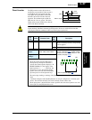
Power
supply
[FW]
Output
frequency
When USP is ON after powerup, the
alarm (E13) will clear when the Run
command (FW or RV) turns OFF.
[USP]
[RS]
Alarm
If the alarm is cleared
during Run command,
the inverter output
restarts automatically.
If the Run command is
already OFF at powerup,
the inverter output starts
normally.
Example 1 Example 2 Example 3
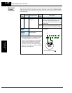
t
5 3 1
7 6 4 2
8
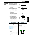
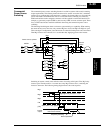
FW
TH
PLC
CM1
P24
CM1
See I/O specs on page 4–9.
Example: (Dfault input configuration
shown for -FU models; -FE and -F models
require input configuration—
see page 3–47
. Jumper position shown is
for –xFU/-xFR models; for –xFE models,
see page 4–12
.)
USP